
Fuel gas ball valve

Inactive Publication Date: 2020-02-21
浙江格扬热工装备科技有限公司
View PDF1 Cites 1 Cited by
  • Summary
  • Abstract
  • Description
  • Claims
  • Application Information

AI Technical Summary

Problems solved by technology

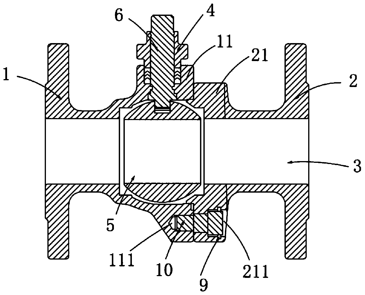
[0005] In view of the above problems, the present invention provides a gas ball valve, which is connected by counterbore screws between the valve body and the gland, and between the valve body and the valve cover, and then sealed with paraffin, which solves the problem of the traditional ball valve having a low service life and being prone to rust. Technical problems, play a role in safety protection and prolong the service life of the valve

Method used


Image

  • Fuel gas ball valve
  • Fuel gas ball valve
  • Fuel gas ball valve

Examples


Embodiment 1

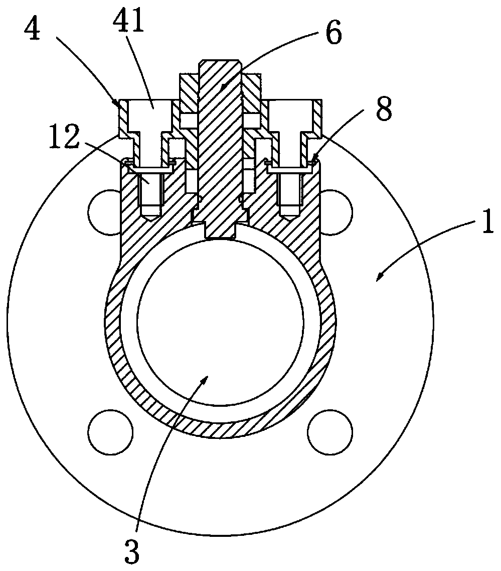
[0032] Such as figure 1 , 2 Shown in and 3, a kind of gas ball valve, it comprises:

[0033] A valve body 1, the valve body 1 is hollow, and the valve body 1 is provided with a connecting plate 11;

[0034] Gland 2, the gland 2 is hollow, and it is set in cooperation with the valve body 1, the valve body 1 and the gland 2 are combined to form a valve body flow channel 3, the gland 2 is provided with a pressure plate 21, The pressing plate 21 is attached to the connecting plate 11, and is connected to the valve body 1 through the counterbore screw 10. The pressing plate 21 is provided with a first counterbore 211, and the first counterbore 211 runs through the A pressing plate 21, and it accommodates the counterbore screw 10, and the first counterbore 211 is sealed with paraffin;

[0035] The valve cover 4, the valve cover 4 is arranged above the valve body 1, and it is connected to the valve body 1 through the counterbore screw 10, the valve cover 4 runs through the valve c...

Embodiment 2

[0044] Figure 5 It is a structural schematic diagram of Embodiment 2 of a gas ball valve of the present invention; Figure 5 As shown, the parts that are the same as or corresponding to those in Embodiment 1 use the reference numerals corresponding to Embodiment 1. For the sake of simplicity, only the differences from Embodiment 1 will be described below. This embodiment two and figure 1 The difference of the shown embodiment one is:

[0045] Such as Figure 5 As shown, the ball valve also includes a handle 7, which is arranged on the upper part of the valve stem 6, and drives the valve stem 6 to rotate synchronously.

[0046] It should be noted that, in this embodiment, the setting of the handle enables the staff to easily control the degree of opening and closing of the ball valve, thereby controlling the flow in the valve body and reducing manual labor.

[0047] work process:

[0048]The valve body 1 and the gland 2 are connected and fixed by countersunk screws 10. Th...


PUM


Abstract

The invention relates to a fuel gas ball valve. The fuel gas ball valve comprises a valve body, a gland, a valve deck, a valve ball and a valve rod, wherein a connecting plate is arranged on the valvebody, the gland is matched with the valve body, and a valve body runner is formed by combining the valve body and the gland; a pressing plate is arranged on the gland, the gland is connected with thevalve body through a countersunk screw, a first counter bore is formed in the pressing plate, the countersunk screw is contained in the first counter bore, the valve deck is arranged above the valvebody and connected with the valve body through a countersunk screw, a second counter bore is formed in the valve deck and runs through the valve deck, and the countersunk screw is contained in the second counter bore; the valve ball is rotationally arranged inside the valve body runner; the valve rod penetrates through the valve deck to be rotationally arranged inside the valve body and is connected with the valve ball, and the valve ball synchronously rotates along with the valve rod. Due to the fact that the valve body and the gland are connected through the countersunk screw, the valve bodyand the valve deck are connected through the countersunk screw, and sealing is performed through paraffin, safety protection is achieved, and the service life of the valve is prolonged.

Description

technical field [0001] The invention relates to the field of valves, in particular to a gas ball valve. Background technique [0002] Gas ball valve is a valve commonly used in natural gas and gas pipelines. Its working principle is: when the rotary handle (or other driving device) is manually operated, with the rotation of the handle, the valve stem and the valve ball are driven to rotate together. As long as the rotation is 90°, the purpose of opening or closing can be achieved. Its advantages are Simple structure, convenient operation, quick opening and closing. However, in actual use, the valve products are carbon steel castings, which are prone to rust at the joints of the valve body, gland and valve cover, which reduces the role of safety protection and at the same time reduces the service life of the valve. [0003] In the invention with the application number CN200620032099.4, a gas ball valve suitable for opening and closing devices in pipelines of natural gas, co...

Claims


Application Information

Patent Timeline
Patent Type & Authority Applications(China)
IPC IPC(8): F16K5/06F16K5/08F16K27/06F16K27/12F16K31/60
CPCF16K5/06F16K5/0647F16K27/067F16K27/12F16K31/60
Inventor 卜杭杭
Owner 浙江格扬热工装备科技有限公司
Learn More