Overload protection type harmonic speed reducer

A harmonic reducer and overload protection technology, which is applied to portable hoisting devices, hoisting devices, transmission parts, etc., can solve the problems of reduced service life of gears, fatigue breakage, poor heat dissipation, etc., to prolong service life and reduce The effect of stabilizing friction and gear tooth friction performance

Pending Publication Date: 2020-02-21
东莞市领亚自动化科技有限公司
View PDF0 Cites 0 Cited by
  • Summary
  • Abstract
  • Description
  • Claims
  • Application Information

AI Technical Summary

Problems solved by technology

[0008] Aiming at the deficiencies of the prior art, the present invention provides an overload-protected harmonic reducer, which solves the problem that the flexible spline deforms periodically when the existing harmonic reducer is working, thus generating alternating stress, making it easy to Fatigue breakage occurs, the heat dissipation is poor, and the heat generated by the harmonic reducer is difficult to dissipate in time, which affects the friction performance of the shaft and the bearing, shortens the service life of the harmonic reducer, and poor lubrication conditions, friction between gears large, reducing the service life of the gear

Method used


Image

  • Overload protection type harmonic speed reducer
  • Overload protection type harmonic speed reducer
  • Overload protection type harmonic speed reducer

Examples


Embodiment

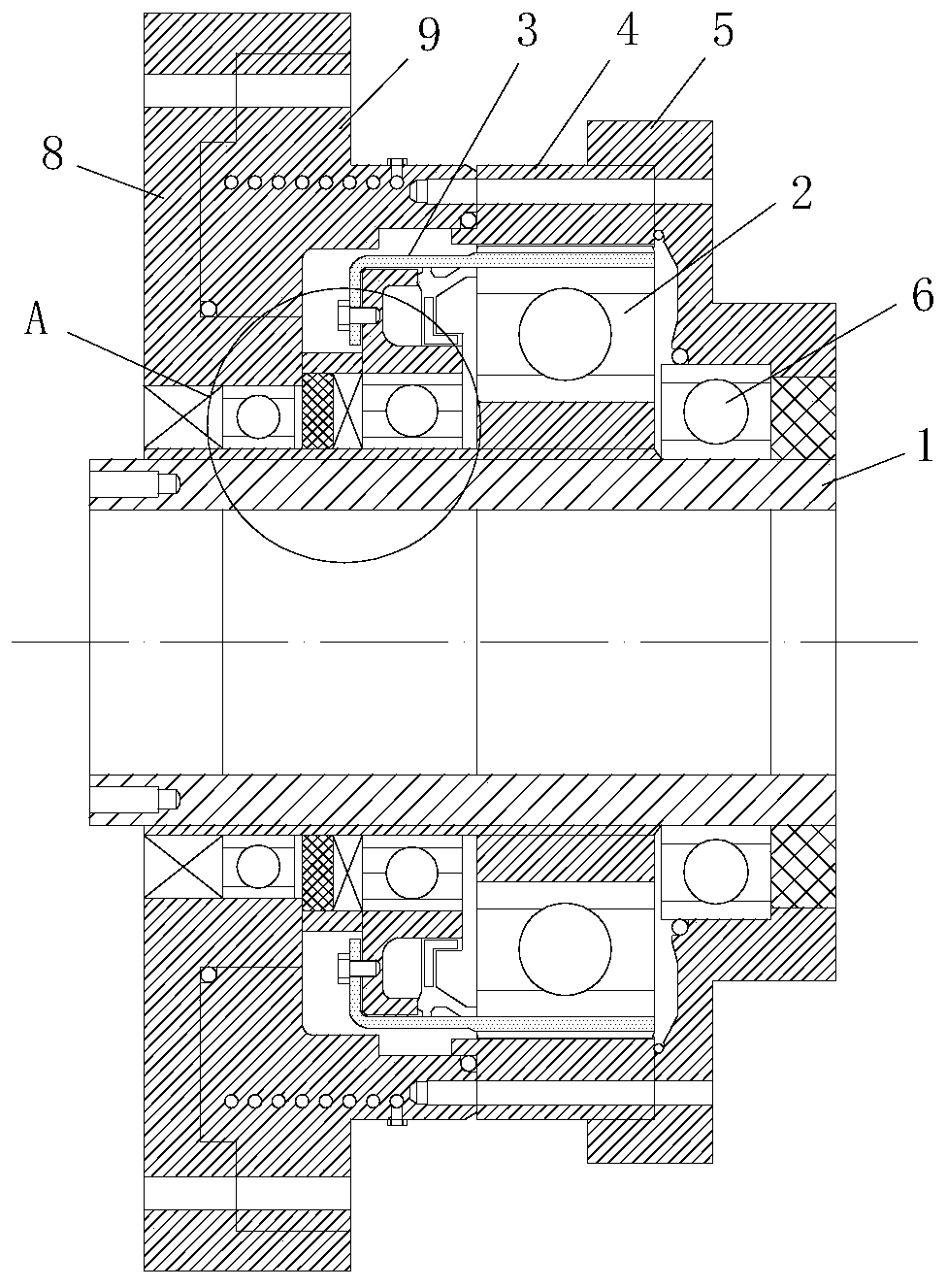
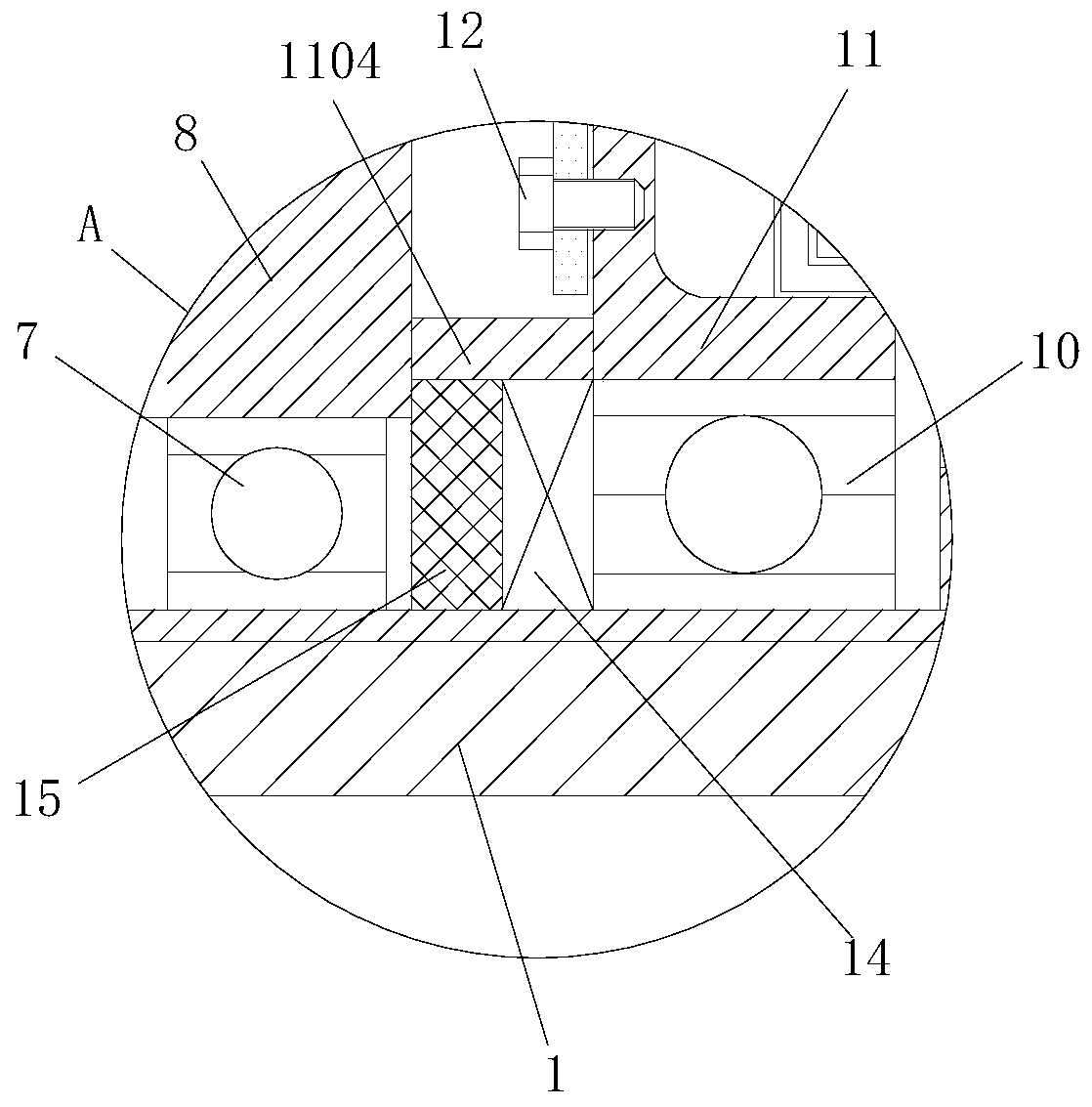
[0032] see Figure 1-5 , the present invention provides the following technical solutions: an overload protection type harmonic reducer, including a wave generator 2 coaxially arranged, a flexible wheel 3 and a steel wheel 4, the front end of the flexible wheel 3 is engaged with the steel wheel 4, and the wave generation The cam of the generator 2 is connected with the input shaft 1, the side of the input shaft 1 corresponding to the wave generator 2 is installed with the first end cover 5 through the rotation of the first bearing 6, and the corresponding wave generator 2 on the input shaft 1 is away from the first end One side of the cover 5 is rotated by the second bearing 7 to install the second end cover 8, and the cooling cover gland 9 is connected between the second end cover 8 and the steel wheel 4, and the cooling cover gland 9 is provided with a coolant inlet 901 and the coolant outlet 902, the inside of the cooling cover gland 9 is provided with a water cooling passa...


PUM


Abstract

The invention belongs to the technical field of harmonic speed reducers and particularly relates to an overload protection type harmonic speed reducer. The overload protection type harmonic speed reducer comprises a wave generator, a flexible wheel and a steel wheel which are arranged coaxially. The front end of the flexible wheel is engaged with the steel wheel, an input shaft is connected to theinterior of a cam of the wave generator, a first end cover is installed on the side, corresponding to the wave generator, of the input shaft in a rotating mode through a first bearing, and a second end cover is installed on the part, corresponding to the side, away from the first end cover, of the wave generator, on the input shaft in a rotating mode through a second bearing. According to the overload protection type harmonic speed reducer, overload protection can be provided for the flexible wheel, the flexible wheel is not prone to fatigue damage, and the service life of the flexible wheelis effectively prolonged; cooling liquid can be used for carrying out heat exchange with heat generated in the working process of the resonance speed reducer, and the quick cooling effect can be achieved; and a lubricating agent can be forced to wriggle and is supplied in a set path, the purpose of reducing friction is achieved, the stability of the wheel-tooth friction performance of the flexiblewheel and the steel wheel is ensured, and the service life of a gear is prolonged.

Description

technical field [0001] The invention relates to the technical field of harmonic reducers, in particular to an overload protection type harmonic reducer. Background technique [0002] The harmonic reducer is mainly composed of four basic components: wave generator, flexible gear, flexible bearing and rigid gear. A gear transmission in which gears mesh to transmit motion and power. The working principle of the harmonic reducer is: the structure and motion principle of the wave generator is similar to that of a cam. The high-speed rotary motion from the mechanism is input to the high-speed shaft in the harmonic reducer. The wave generator is linked with the high-speed shaft, through its own The shape of the outer contour line of the wave generator transmits the motion to the flexible wheel; as the name suggests, the flexible wheel is a flexible external gear that can undergo controllable elastic deformation. With the rotation of the wave generator, the flexible wheel performs ...

Claims


Application Information

Patent Timeline
IPC IPC(8): F16H49/00F16H57/023F16H57/029F16H57/021F16H57/04F16H55/17F16H55/08
CPCF16H49/001F16H55/0833F16H55/17F16H57/021F16H57/023F16H57/029F16H57/0412F16H57/042
Inventor 陈玉敏
Owner 东莞市领亚自动化科技有限公司
Why Eureka
Try Eureka