
Tank body used for storing printing ink

A technology for storing ink and tanks, applied in tank cars, railway car body parts, transportation passenger cars, etc., can solve the problems of heavy labor load of operators, affecting ink quality, and inability to clean ink, and achieve efficient and reliable cleaning, efficient and fast cleaning. , the effect of reducing labor load

Inactive Publication Date: 2020-02-21
XUZHOU SUNUP INK CHEM
View PDF5 Cites 3 Cited by
  • Summary
  • Abstract
  • Description
  • Claims
  • Application Information

AI Technical Summary

Problems solved by technology

[0002] After the ink is produced, it needs to be stored in the tank, and after a certain period of storage, it often produces precipitation or agglomeration. If this situation is not dealt with, the quality of the ink will be affected
[0003] The existing solution is to use the stirring rod to stir manually from time to time, but this method cannot effectively clean the ink attached to the inner wall of the tank, so the stirring effect is not ideal, and there will still be precipitation or agglomeration The phenomenon
Since the agglomeration phenomenon on the inner wall of the tank cannot be cleaned up effectively and in a timely manner, it will affect the re-use of the subsequent tank body, and at the same time, it is necessary to waste a lot of manpower and material resources to deal with the agglomeration on the inner wall of the tank
Simultaneously, the labor load of the operator of this processing method is relatively large

Method used


Image

  • Tank body used for storing printing ink

Examples


Embodiment Construction

[0014] The present invention will be further described below in conjunction with accompanying drawing.

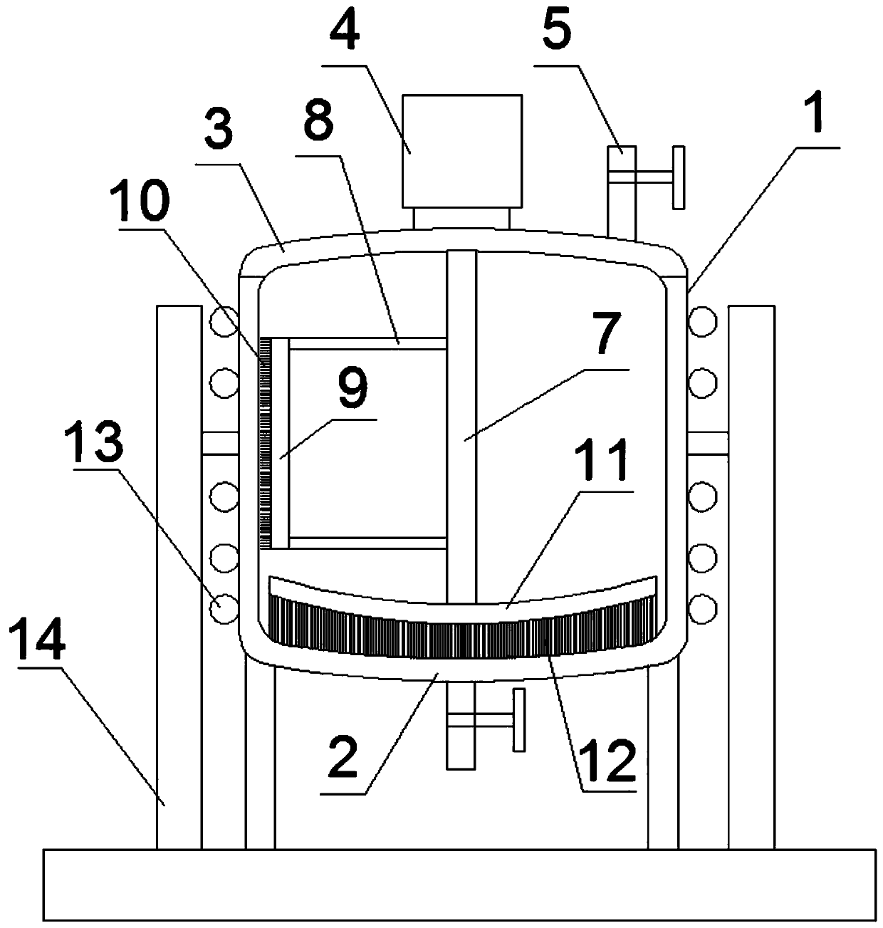
[0015] Such as figure 1 As shown, a tank body for storing ink includes a tank body body 1, the tank body body 1 is a cylindrical body whose bottom is closed by a bottom plate 2, and a sealing cover plate 3 is arranged on the upper end of the tank body, and the central area of ​​the airtight cover plate A stirring motor 4 is fixedly connected, one side of which is connected with a liquid inlet pipeline 5 connected to the inner cavity of the tank main body 1, and the central area of ​​the bottom plate 2 is fixedly connected with a liquid outlet pipeline 6 communicated with the inner cavity;

[0016] The inner axis of the tank body 1 is provided with a stirring shaft 7, and the upper end of the stirring shaft 7 rotatably passes through the sealing cover plate 3 and is connected with the output end of the stirring motor 4;

[0017] On the same side of the stirring shaft 7, a p...


PUM


Abstract

The invention discloses a tank body used for storing printing ink. A sealing cover plate is arranged at the upper end of a main tank body. A stirring motor is fixedly connected to the center area of the sealing cover plate. A stirring shaft is arranged at the inner axis position of the main tank body. The upper end of the stirring shaft rotationally penetrates the sealing cover plate and is connected with the output end of the stirring motor. A pair of connecting beams are fixedly connected to the same side of the stirring shaft in a spaced manner in the up-down direction. The left ends of thepair of connecting beams are fixedly connected with the inner side of a scraping plate which is vertically arranged, the scraping plate is arranged close to the side wall of the main tank body, and the outer side face of the scraping plate is connected with multiple hard bristles A in the length direction of the scraping plate. The hard bristles A are matched with the side wall of the main tank body in a contact manner. An arc stirring rod is fixedly connected to the bottom end of the stirring shaft, the stirring rod is arranged close to a bottom plate, multiple hard bristles B are connectedto the lower portion of the stirring rod in the length direction of the stirring rod, and the hard bristles are matched with a bottom plate in a contact manner. By means of the tank body, the phenomenon of precipitation or agglomeration which is likely to happen due to long-term storage can be effectively dealt with, and in addition, the labor load of workers can be reduced.

Description

technical field [0001] The invention relates to a tank body for storing ink. Background technique [0002] After the ink is produced, it needs to be stored in a tank, and after a certain period of storage, precipitation or agglomeration often occurs. If this situation is not dealt with, the quality of the ink will be affected. [0003] The existing solution is to use the stirring rod to stir manually from time to time, but this method cannot effectively clean the ink attached to the inner wall of the tank, so the stirring effect is not ideal, and there will still be precipitation or agglomeration The phenomenon. Since the agglomeration phenomenon on the inner wall of the tank cannot be cleaned up effectively and in time, it affects the re-use of the subsequent tank body, and at the same time, a large amount of manpower and material resources need to be wasted to deal with the agglomeration on the inner wall of the tank. Simultaneously, this processing mode operator's labor...

Claims


Application Information

Patent Timeline
Patent Type & Authority Applications(China)
IPC IPC(8): B65D88/74B65D88/54B65D90/00
CPCB65D88/54B65D88/744B65D90/00
Inventor 李广海
Owner XUZHOU SUNUP INK CHEM
Learn More