
A waste tire recycling and dividing machine

A waste tire and dividing machine technology, applied in the direction of plastic recycling, recycling technology, etc., can solve the problems of large floor space and difficult handling, and achieve the effect of saving space, ensuring service life and facilitating recycling.

Active Publication Date: 2021-08-24
徐州宏昌企业管理咨询服务有限公司
View PDF8 Cites 0 Cited by
  • Summary
  • Abstract
  • Description
  • Claims
  • Application Information

AI Technical Summary

Problems solved by technology

[0005] In order to overcome the disadvantages that tires occupy a large area, require more vehicles to carry and carry, and are difficult to carry, the technical problem to be solved is: to provide a tire that can reduce the volume and does not require too many vehicles for loading. Waste tire recycling and splitting machine that is easy to carry after splitting

Method used


Image

  • A waste tire recycling and dividing machine
  • A waste tire recycling and dividing machine
  • A waste tire recycling and dividing machine

Examples


no. 1 example

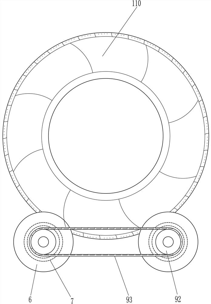
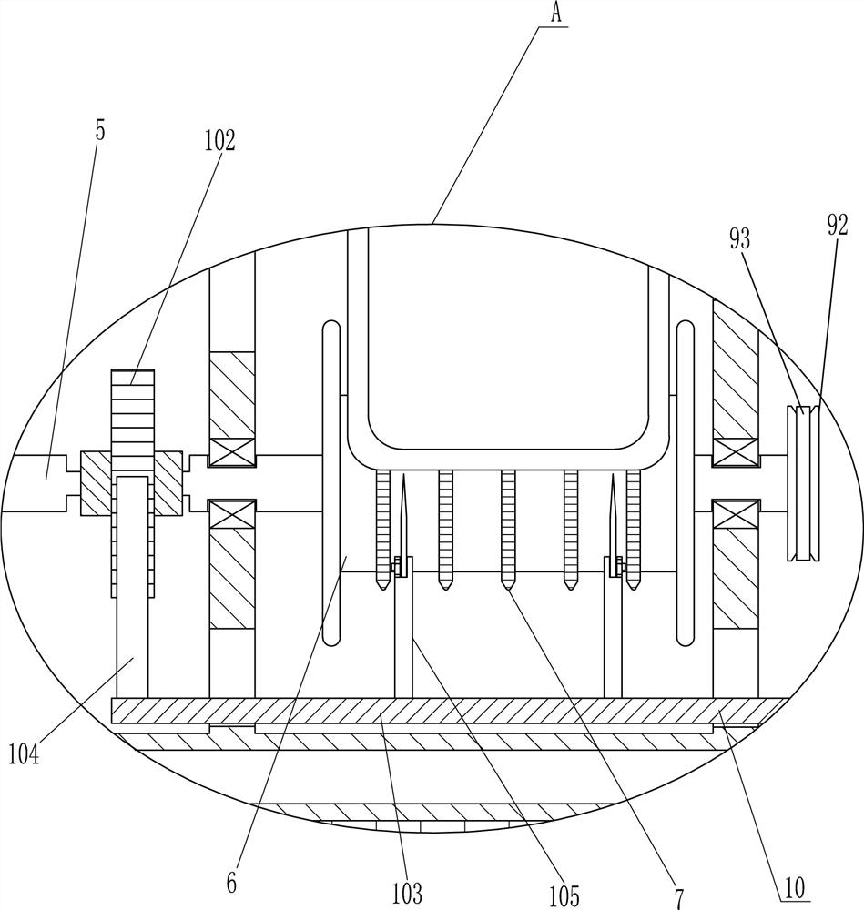
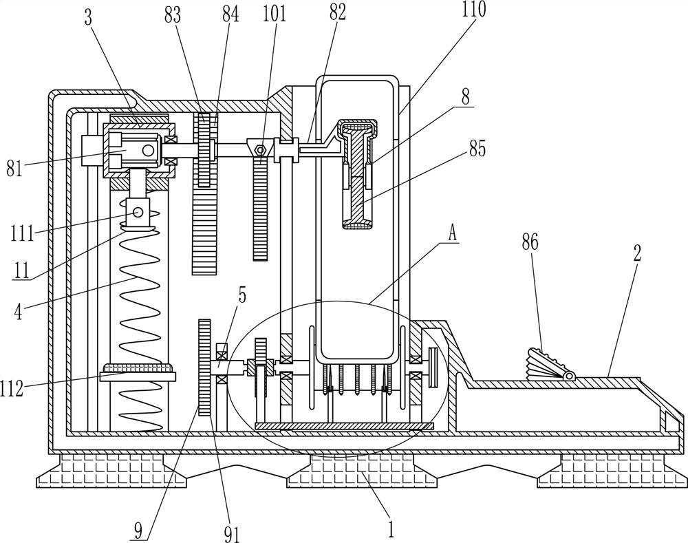
[0018] see Figure 1-3 , a waste tire recycling and dividing machine, including a base 1, a casing 2, a sliding frame 3 and a compression spring 4, the base 1 is provided with a casing 2, and the left side of the casing 2 is slidingly provided with a sliding frame 3, sliding The frame 3 can slide up and down in the casing 2, and a compression spring 4 is connected between the bottom of the sliding frame 3 and the inner bottom of the casing 2, and also includes a rotating shaft 5, a roller 6, a transmission gear ring 7, a pressing assembly 8, a rotating Component 9 and cutting component 10, the inner bottom of the casing 2 is equipped with a rotating shaft 5 symmetrically rotating on the front and rear sides, the rotating shaft 5 is parallel to the base 1, and rollers 6 are arranged on the rotating shaft 5, and there are multiple circles evenly spaced on the rollers 6 The transmission gear ring 7, the transmission gear ring 7 is connected with the roller 6 through a key connect...

no. 2 example

[0027] Based on the first example, please refer to Figure 1-3 , also includes an adsorption assembly 11, the adsorption assembly 11 includes an electromagnet 111 and an iron block 112, an electromagnet 111 is installed at the bottom of the sliding frame 3, the electromagnet 111 is electrically connected with the foot switch 86, and the lower part of the casing 2 is provided with An iron block 112 , the iron block 112 is located below the electromagnet 111 .

[0028] By stepping on the foot switch 86, the electromagnet 111 starts, and when the drive gear 83 engages, the electromagnet 111 is adsorbed on the iron block 112, so that people do not need to always press the sliding frame 3, which makes the operation easier. After finishing, unclamp pedal switch 86, electromagnet 111 disconnects energization, under the effect of compression spring 4, sliding frame 3 resets upwards.


PUM


Abstract

The invention relates to a dividing machine, in particular to a recycling and dividing machine for waste tires. The technical problem to be solved is how to provide a waste tire recycling and splitting machine that can reduce the volume of tires, does not require too many vehicles to load, and is easy to carry after splitting. A waste tire recycling and dividing machine, including a base, a casing, a sliding frame, a compression spring, a rotating shaft, a roller, a transmission gear ring, etc.; There is a compression spring connected between the frame and the sliding frame and the casing, and a rotating shaft is arranged symmetrically on the front and rear sides of the bottom of the casing, and rollers are arranged on the rotating shafts, and multiple transmission gear rings are evenly spaced on the rollers. In the invention, the tire is pressed down by the pressing component to ensure the stability of the work, and at the same time, the rotating component indirectly drives the tire to rotate through the transmission, and then the tire is divided by the cutting component.

Description

technical field [0001] The invention relates to a dividing machine, in particular to a recycling and dividing machine for waste tires. Background technique [0002] With the gradual improvement of people's living standards and the rapid development of the logistics industry, the number of private cars and trucks in my country has increased year by year. The increase in the number of vehicles has driven the development of the economy, and the consumption and wear of automobile tires has also produced a lot of garbage - waste tires. A few years ago, waste tires were thrown away as garbage, which greatly polluted the environment on which we live, so the recycling of waste tires is a very important key point. [0003] At present, waste tires are usually stored in an open space or in a storage warehouse so that they can be accumulated and sold to corresponding processing plants for crushing and refining, and further processing is carried out. However, due to the large size of ti...

Claims


Application Information

Patent Timeline
Patent Type & Authority Patents(China)
IPC IPC(8): B29B17/04
CPCB29B17/04B29B2017/044Y02W30/62
Inventor 吴冈泽
Owner 徐州宏昌企业管理咨询服务有限公司
Learn More