


Quick Research
Generate reliable direction feasibility study reports for your R&D in just a few steps.

Technical Q&A
Discover and master advanced knowledge NOW. Basics, ideas, possibilities, all at once.

Find Solutions
As an expert in R&D theories, this can generate solutions to your technical problems instantly.

Evaluate Feasibility
Analyze your overall solution with one click, know your potential R&D risks in advance.

Monitor Landscape
Get weekly tech updates, stay abreast of the latest tech innovations and key insights.
A five-degree-of-freedom parallel mechanism with double-actuated composite branches
A dual-drive, degree-of-freedom technology, applied to manipulators, program-controlled manipulators, manufacturing tools, etc., can solve the problem of reducing the working space of motion and achieve the effect of large working space
- Summary
- Abstract
- Description
- Claims
- Application Information
AI Technical Summary
Problems solved by technology
Method used
Image

Examples
Embodiment 1
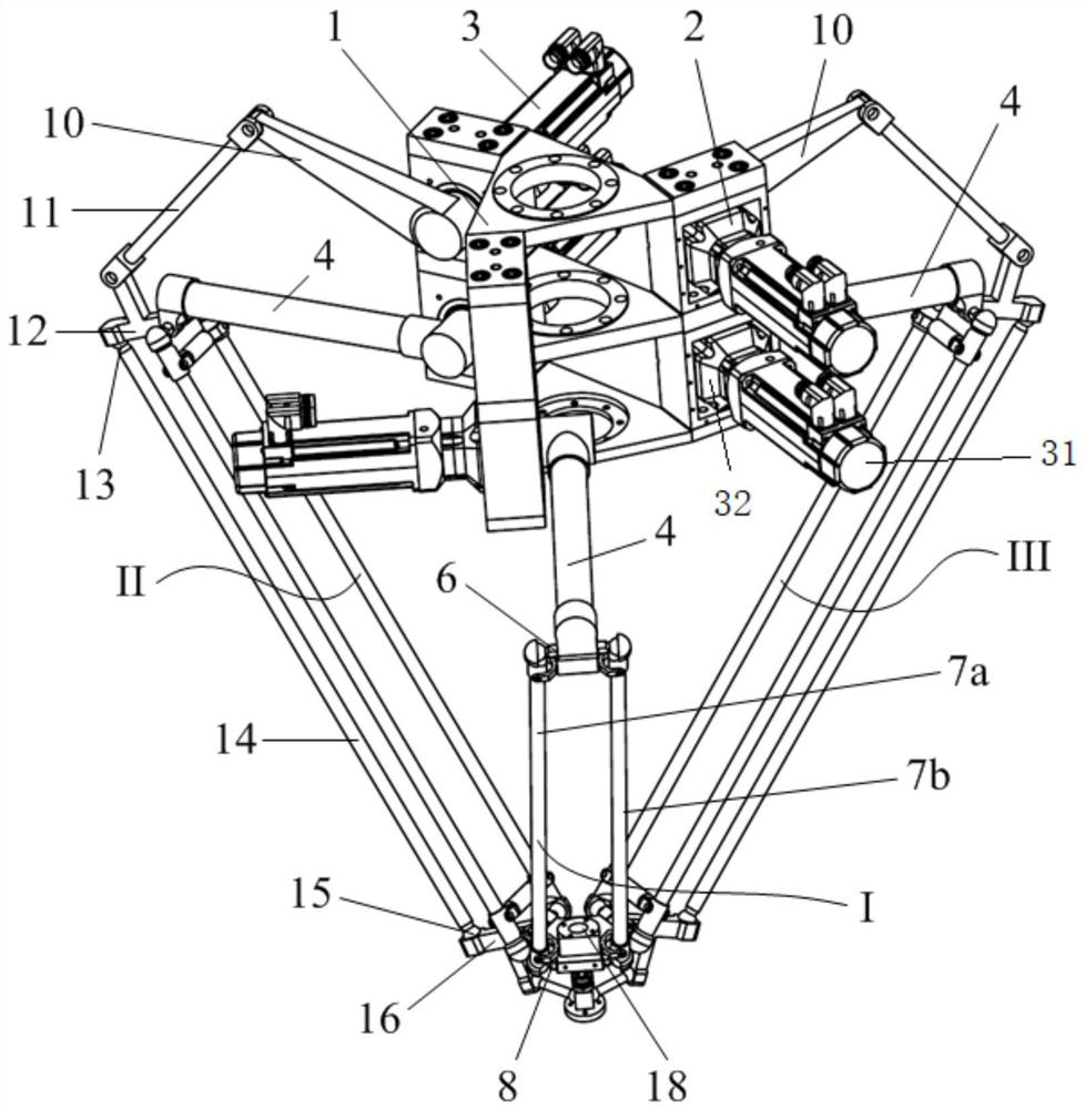
[0027] to combine figure 1 , figure 2 , a five-degree-of-freedom parallel mechanism containing a double-drive composite branch chain in this embodiment, including a static platform 1, a moving platform 18, an end effector 23, and three branch chains connected in parallel between the static platform 1 and the moving platform 18 In the three branch chains connected in parallel between the static platform 1 and the dynamic platform 18, two branch chains are double-drive branch chains, and one is a single-drive branch chain; the double-drive branch chains include the main drive branch chain and the main drive branch chain The secondary drive branch on the drive branch; the end effector 23 is connected to the moving platform 18 through a Hooke hinge 22 .
[0028] Among the three branch chains connected in parallel between the static platform 1 and the moving platform 18, the first branch chain is a single drive branch chain 1, including the first drive motor 31, the first speed r...
Embodiment 2
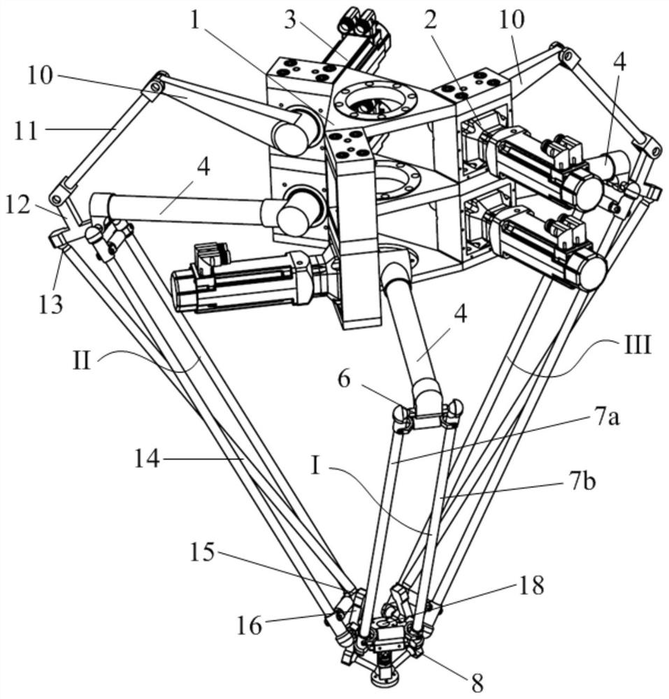
[0033] The structure of this embodiment is as Figure 3(a) , 3(b) As shown, different from Embodiment 1, the driven link 14 in the double drive branch chain II and III of this embodiment is arranged crosswise with the two connecting rods 7a and 7b in the space quadrilateral mechanism, that is, the two connecting rods 7a and 7b in the space quadrilateral mechanism The projection lines of the connecting rods 7a and 7b on the plane perpendicular to the secondary axis of rotation of the first active arm 4 coincide with each other, and the projection line is the same as that of the driven connecting rod 14 on the plane perpendicular to the secondary axis of rotation of the first active arm 4. Projection lines cross each other.
Embodiment 3
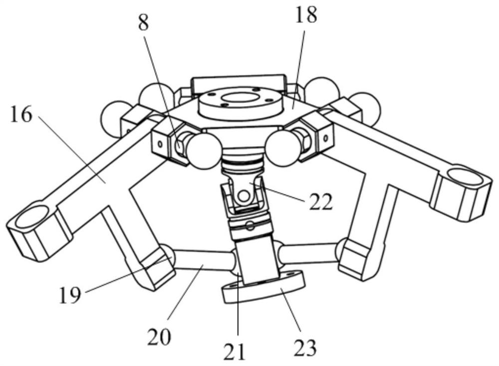
[0035] The structure of this embodiment is shown in FIG. 4( a ). The difference between this embodiment and Embodiment 1 is that the arrangement of the moving platform 18 is different.
[0036]As shown in Figure 4(b), there is an opening at the center of the moving platform 18, the active end of the Hooke hinge 22 is fixedly connected to the center of the moving platform 18, and the axis of the active end coincides with the center plane of the moving platform 18, and the end effector 23 passes through the center of the moving platform 18 and is fixedly connected with the passive end of the Hooke hinge 22. The connecting rod 20 is arranged above the moving platform 18 and its two ends are respectively connected to the second connecting member 16 and the end effector 23 through a spherical joint.
PUM
 Abstract
Description
Claims
Application Information
 - R&D Engineer
- R&D Manager
- IP Professional
- Industry Leading Data Capabilities
- Powerful AI technology
- Patent DNA Extraction
Browse by: Latest US Patents, China's latest patents, Technical Efficacy Thesaurus, Application Domain, Technology Topic, Popular Technical Reports.
© 2024 PatSnap. All rights reserved.Legal|Privacy policy|Modern Slavery Act Transparency Statement|Sitemap|About US| Contact US: help@patsnap.com