Eureka AIR delivers breakthrough ideas for toughest innovation challenges, trusted by R&D personnel around the world.

End-expiratory CO2 guided tracheal intubation apparatus

A technology for endotracheal intubation and end-expiration, which is applied in the direction of tracheal intubation, respirator, suction equipment, etc. It can solve the problems of speculum visual barriers and affect intubation insertion, so as to facilitate observation, improve work efficiency, and prevent damage effect

Active Publication Date: 2020-02-21
SHANGHAI NINTH PEOPLES HOSPITAL SHANGHAI JIAO TONG UNIV SCHOOL OF MEDICINE
View PDF9 Cites 1 Cited by
  • Summary
  • Abstract
  • Description
  • Claims
  • Application Information

AI Technical Summary

Problems solved by technology

[0003] Existing endotracheal intubation is inserted into the laryngeal tube through the intubation tube and the speculum, and the larynx is observed through the speculum to find the trachea, and then the intubation tube is inserted into the laryngeal tube, but during the intubation process, the laryngeal tube and the trachea Pus will be secreted, and fluid accumulation will form in the larynx and trachea, which will cause visual disturbance to the speculum and affect the insertion of the intubation tube

Method used


Image

  • End-expiratory CO2 guided tracheal intubation apparatus
  • End-expiratory CO2 guided tracheal intubation apparatus
  • End-expiratory CO2 guided tracheal intubation apparatus

Examples


Embodiment 1

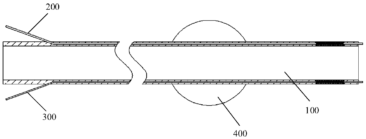
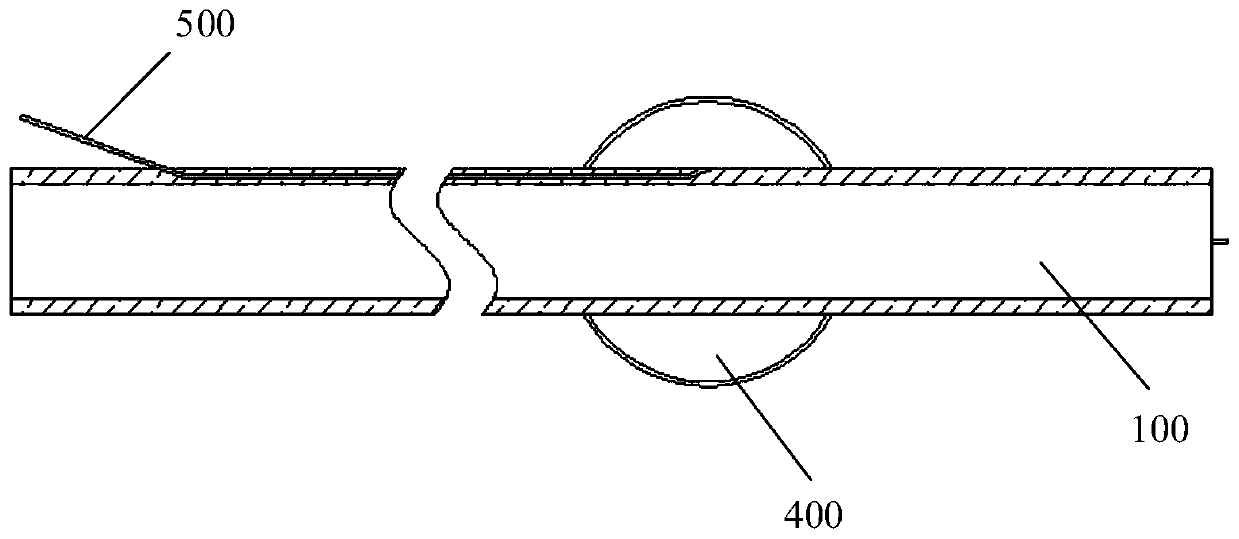
[0028] Such as figure 1 with figure 2 As shown, an end-tidal CO provided by an embodiment of the present invention 2 Guide tracheal intubation device, including: intubation 100, end-tidal CO 2 The catheter 200, the pipette 300, the balloon 400, and the inflation tube 500. End-tidal CO 2 The catheter 200 is partially inserted into the side wall of the cannula 100, and one end extends beyond the end of the cannula 100, and the other end is connected to the end-tidal CO 2 The sensor is connected; the pipette 300 is partially penetrated in the side wall of the cannula 100, and one end extends outside the end of the cannula 100, and the other end is connected to the air pump. In this example, the end-tidal CO 2 One end of the catheter 200 enters the side wall of the cannula 100 from somewhere near the left end of the cannula 100, and extends to the right in the side wall and penetrates the right end surface of the cannula 100. 2 The other end of the catheter 200 and the end-tidal CO ...

Embodiment 2

[0040] The similarities between this embodiment and the first embodiment will not be repeated. Such as Figure 5 to Figure 7 As shown, the end-tidal CO is provided in the side wall of the cannula 100 2 Conduit installation slot 110. End-tidal CO 2 The catheter 200 includes a first end pipe section 210, a first section pipe section 220, and a first tail pipe section 230 that are sequentially connected; the first end pipe section 210 is connected to the end-tidal CO 2 Sensor connection; the first tube section 220 is set at the end-tidal CO 2 The catheter installation groove 110 is sheathed with a first spring 600. One end of the first spring 600 is in contact with the first stop 240 provided on the first tail pipe section 230, and the other end is in contact with the end-expiratory CO 2 The end wall of the catheter installation groove 110 abuts; the first tail pipe section 230 extends to the outside of the cannula 100. In this embodiment, the right end of the cannula 100 is inser...


PUM


Abstract

The invention discloses an end-expiratory CO2 guided tracheal intubation apparatus. The apparatus comprises: an intubation pipe, an end-expiratory CO2 guide pipe, a liquid suction pipe, an air bag andan air-changing air pipe, wherein the end-expiratory CO2 guide pipe is arranged in the side wall of the intubation pipe in a partial penetrating manner, one end of the end-expiratory CO2 guide pipe extends beyond the terminal end of the intubation pipe, the other end of the end-expiratory CO2 guide pipe is connected with an end-expiratory CO2 sensor, the liquid suction pipe is arranged in the side wall of the intubation pipe in a partial penetrating manner, one end of the liquid suction pipe extends beyond the terminal end of the intubation pipe, the other end of the liquid suction pipe is connected with an air pump, the air bag sleeves the outer wall of the intubation pipe, the air-changing air pipe is arranged in the side wall of the intubation pipe, one end of the air-changing air pipeenters the inside of the air bag, and the other end of the air-changing air pipe is connected with an air supply apparatus. According to the apparatus, the tracheal intubation position is quickly andaccurately determined by detecting the end-expiratory CO2 data of an exhaled gas of the patient's throat through the end-expiratory CO2 guide pipe arranged in the intubation pipe wall, and cooperating with an endoscope. In addition, the effusion in the throat and trachea of a patient is drawn out through the liquid suction pipe, and thereby the observation of the medical personnel with the endoscope is facilitated.

Description

Technical field [0001] The present invention relates to the technical field of medical devices, in particular to an end-tidal CO 2 Guide the tracheal intubation device. Background technique [0002] Tracheal intubation refers to the insertion of a special endotracheal tube into the trachea through the glottis. This technology can provide the best conditions for airway patency, ventilation and oxygen supply, airway suction and prevention of aspiration. Emergency tracheal intubation has become an important measure in the rescue of critically ill patients with cardiopulmonary resuscitation and respiratory dysfunction. Tracheal intubation is an important rescue technique commonly used in emergency work. It is one of the most widely used, most effective and quickest methods in respiratory management. It is a basic skill that medical staff must master. It is useful for saving patients’ lives and reducing mortality. Play a vital role. [0003] The existing tracheal intubation is inserte...

Claims


Application Information

Patent Timeline
Patent Type & Authority Applications(China)
IPC IPC(8): A61M16/04A61M1/00
CPCA61M1/0023A61M16/0402A61M2230/40A61M2230/005A61M16/04A61M16/0434A61M16/0463A61M16/0477A61M2210/1032A61M16/0486A61M2016/0413A61M16/0003A61M16/045A61M16/0488
Inventor 姜虹夏明孙宇严佳
Owner SHANGHAI NINTH PEOPLES HOSPITAL SHANGHAI JIAO TONG UNIV SCHOOL OF MEDICINE
Why Eureka
Eureka Blog
Learn More