External fixator for limb fractures
An external fixator and fixator technology, applied in the field of medical devices, can solve the problems of single function, difficult nursing and complicated structure of the ring external fixator system, and achieve the effect of reducing surgical injury, reducing operation time, and simple operation
- Summary
- Abstract
- Description
- Claims
- Application Information
AI Technical Summary
Problems solved by technology
Method used
Image
Examples
specific Embodiment approach 1
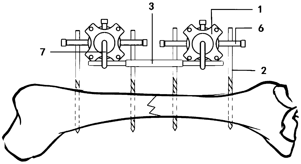
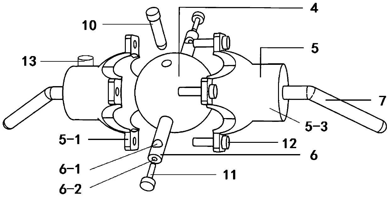
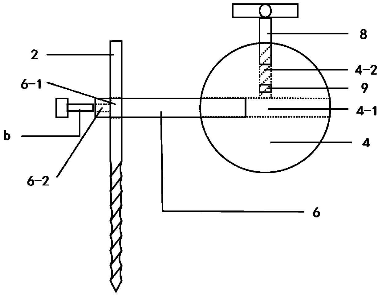
[0029] Specific implementation mode one: combine Figure 1-Figure 5 Describe this embodiment, an external fixator for extremity fractures in this embodiment, including two or more reduction fixators 1, four or more bone pins 2, two or more telescopic rods 3, two or more The spicule fixing rod 6, four or more curved rod pillars 7 and a plurality of auxiliary reset rods 8 are used in conjunction, the bone spicule fixing rod 6 is installed on the reset fixer 1, and there is a fixing hole 6 at both ends of the bone spicule fixing rod 6 -1, the fixing hole 6-1 is used to place and fix the bone needle 2, a curved rod support 7 is respectively installed on the left and right sides of the reset fixer 1, and the two telescopic rods 3 are respectively connected to the two adjacent reset fixer 1 The bent rod pillar 7 adjusts the relative position of two adjacent reset fixers 1 by adjusting the telescopic rod 3 .
[0030] The reset fixer 1 includes a reset ball 4, a top wire 9 and a fixi...
specific Embodiment approach 2
[0035] Specific implementation mode two: combination Figure 1-Figure 5 Describe this embodiment, a kind of external fixator for extremity fracture of this embodiment, described installation steps are as follows:
[0036]Step 1: After the lower extremity fracture, due to the external force during the injury and the effect of muscle stretching after the injury, the two fracture ends have different degrees of displacement. Physicians can determine the proper insertion position of the bone needle 2 through the preoperative imaging examination and the general fracture movement orientation. First, the two spicules 2 are inserted into the spicule fixing rod 6, and at this time, the spicules 2 and the spicule fixing rod 6 are not locked. Afterwards, the spicules 2 are drilled into the two fracture segments to be fixed. During this process, the spicule fixing rod 6, which is relatively unfixed with the spicules 2, plays a role in determining the distance between the two spicules 2. ...
specific Embodiment approach 3
[0041] Specific implementation mode three: combination Figure 1-Figure 5 Describe this embodiment, a kind of external fixator for extremity fracture of this embodiment, described traction, reduction and fixation steps are as follows:
[0042] Step 1: After completing the installation according to the description of the second embodiment, there are still various forms of displacement at the two fracture ends. Now by rotating the internally threaded rod 3-3 of the telescopic rod, the telescopic rod 3 is extended, and the two fracture ends are retracted. The experience of multiple operations tells us that after the muscle is stretched to a certain length L1, it will not produce more deformation. At this time, if the muscle length is forcibly extended, it will cause muscle damage. However, if the length L1 is maintained for a few minutes at the point of maximum deformation and then increased, the retraction can be extended to the length L2 without damaging the muscle. Therefore...
PUM
 Abstract
Description
Claims
Application Information
 - R&D
- Intellectual Property
- Life Sciences
- Materials
- Tech Scout
- Unparalleled Data Quality
- Higher Quality Content
- 60% Fewer Hallucinations
Browse by: Latest US Patents, China's latest patents, Technical Efficacy Thesaurus, Application Domain, Technology Topic, Popular Technical Reports.
© 2025 PatSnap. All rights reserved.Legal|Privacy policy|Modern Slavery Act Transparency Statement|Sitemap|About US| Contact US: help@patsnap.com


