
A planar far-infrared continuous sterilization dryer

A far-infrared and dryer technology, applied in the direction of dryers, drying, drying solid materials, etc., can solve the problems of low heat and mass transfer efficiency, uncontrollable temperature, etc., to improve drying efficiency, increase heating speed, The effect of increasing the flow distance

Active Publication Date: 2020-11-17
伍晓刚
View PDF8 Cites 0 Cited by
  • Summary
  • Abstract
  • Description
  • Claims
  • Application Information

AI Technical Summary

Problems solved by technology

[0002] Drying equipment is commonly used in various agricultural products and chemical products. Among them, the surface continuous dryer is more common. The material is fed from the feeding port and passes through the conveyor belt, and the material is dried with hot air, and the material is discharged from the feeding port, but its heat transfer Inefficient mass transfer, uncontrollable temperature, and only drying effect

Method used


Image

  • A planar far-infrared continuous sterilization dryer
  • A planar far-infrared continuous sterilization dryer
  • A planar far-infrared continuous sterilization dryer

Examples


Embodiment Construction

[0043] The technical solution of the present invention will be described in detail below in conjunction with the accompanying drawings. Apparently, the following examples are implemented on the premise of the technical solution of the present invention, and detailed implementation is given, but the protection scope of the present invention is not limited to the following examples. Based on the technical solution of the present invention, other embodiments made by those skilled in the art without creative efforts all belong to the protection scope of the present invention. It should be noted that, in the case of no conflict, the embodiments in the present application and the features in the embodiments can be combined with each other.

[0044] In the description of the present invention, it should be noted that the terms "center", "upper", "lower", "left", "right", "vertical", "horizontal", "inner", "outer" etc. The indicated orientation or positional relationship is based on ...


PUM


Abstract

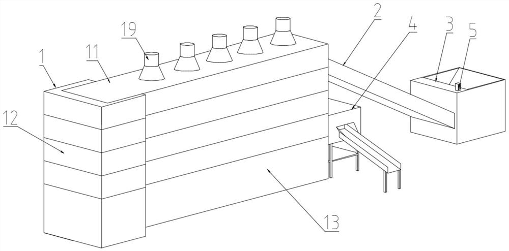
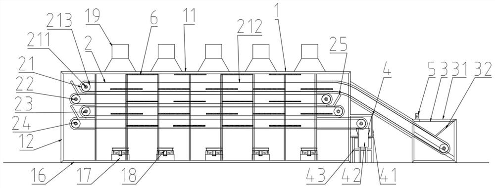
The invention discloses a face-shaped far infrared continuous sterilizing dryer. The face-shaped far infrared continuous sterilizing dryer comprises a drying box, a material transporting system, a loading system, an unloading system, far infrared plates and a control switch; the drying box comprises a top plate provided with an air outlet, a bottom plate provided with an air inlet, a first side plate, a third side plate, a second side plate and a fourth side plate, wherein the first side plate and the third side plate are arranged oppositely, the second side plate and the fourth side plate arearranged oppositely, and an air inlet fan is arranged in the air inlet; the material transporting system comprises a first layer transporting system and a second layer transporting system, the firstlayer transporting system comprises a driving idler wheel, a driven idler wheel, a motor and a conveying belt for connecting the driving idler wheel with the driven idler wheel, the driving idler wheel is arranged in the drying box, the motor is arranged in the driving idler wheel, the second layer transporting system and the first layer transporting system are the same in structure, and the second layer transporting system is arranged on the lower part of the first layer transporting system; and the multiple far infrared plates are arranged between the upper face and the lower face of the conveying belt as well as between the upper face and the lower face of a second conveying belt correspondingly. According to the face-shaped far infrared continuous sterilizing dryer, the drying efficiency is high, the temperature and humidity are controllable, and the sterilizing effect is achieved.

Description

technical field [0001] The invention relates to the field of drying equipment, in particular to a planar far-infrared continuous sterilization dryer. Background technique [0002] Drying equipment is commonly used in various agricultural products and chemical products. Among them, the surface continuous dryer is more common. The material is fed from the feeding port and passed through the conveyor belt, and the material is dried with hot air, and the material is discharged from the feeding port, but its heat transfer The mass transfer efficiency is low, the temperature is uncontrollable, and it only plays a drying role. Contents of the invention [0003] Aiming at the shortcomings of the above-mentioned prior art, the present invention provides a planar far-infrared continuous sterilization dryer, which has high drying efficiency, controllable temperature and humidity, and sterilizing effect. [0004] The technical scheme adopted in the present invention is: [0005] A p...

Claims


Application Information

Patent Timeline
Patent Type & Authority Patents(China)
IPC IPC(8): F26B17/04F26B21/00F26B21/08F26B23/04F26B25/02
CPCF26B17/04F26B21/001F26B21/08F26B23/04F26B25/02
Inventor 伍晓刚朱全勇伍辰星
Owner 伍晓刚
Learn More