
Double pushing type rack

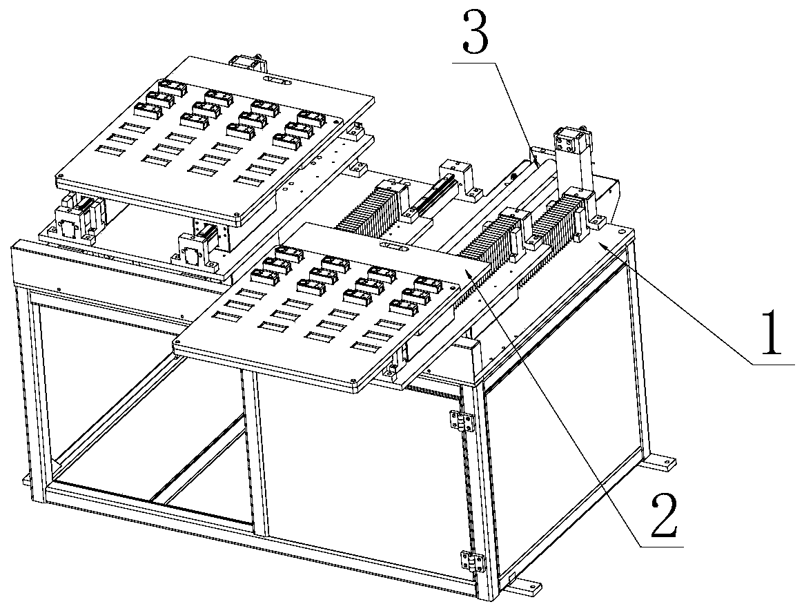
A push-out, material rack technology, applied in the direction of grinding workpiece supports, grinding feed motion, surface polishing machine tools, etc., can solve the problems of pollution, obstacles to the transportation of workers' goods, etc., and achieve the effect of lengthening the push-out distance and saving space.

Pending Publication Date: 2020-02-18
FOSHAN LOGEN ROBOT CO LTD
View PDF0 Cites 0 Cited by
  • Summary
  • Abstract
  • Description
  • Claims
  • Application Information

AI Technical Summary

Problems solved by technology

[0003] In the existing automated production line, industrial robots, tool holders and grinding tables are generally placed in the dust-proof room to prevent the dust generated during the workpiece grinding process from spreading outside the dust-proof room and pollute the environment outside the dust-proof room. In addition, In the workpiece grinding project, workers need to load and unload the material rack, so half of the existing material rack is placed in the dust-proof room, and the other half is placed on the aisle outside the dust-proof room. The material rack generally includes the main board of the rack, the tray and The feeding mechanism, the tray and the feeding mechanism are placed on the main board of the rack. When the worker loads the material, the feeding mechanism pushes the entire tray out of the dust-proof room. After the worker unloads the material, the feeding mechanism pushes the entire tray into the dust-proof room. Half of them are placed on the aisle outside the dustproof room, which will greatly hinder the walking of workers and the transportation of goods

Method used


Image

  • Double pushing type rack
  • Double pushing type rack
  • Double pushing type rack

Examples


Embodiment Construction

[0032]The preferred embodiments of the present invention will be described below in conjunction with the accompanying drawings. It should be understood that the preferred embodiments described here are only used to illustrate and explain the present invention, and are not intended to limit the present invention.

[0033] In the description of the present invention, it should be noted that the terms "center", "upper", "lower", "left", "right", "vertical", "horizontal", "inner", "outer" etc. The indicated orientation or positional relationship is based on the orientation or positional relationship shown in the drawings, and is only for the convenience of describing the present invention and simplifying the description, rather than indicating or implying that the referred device or element must have a specific orientation, or in a specific orientation. construction and operation, therefore, should not be construed as limiting the invention. In addition, the terms "first", "second...


PUM


Abstract

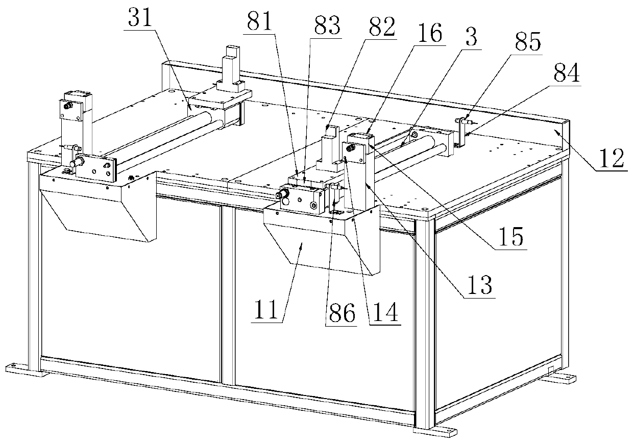
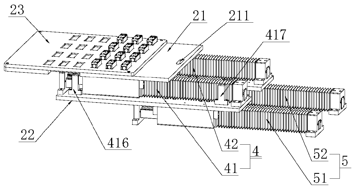
The invention discloses a double pushing type rack which comprises a frame main board; a material frame and an air cylinder are arranged on the frame main board; the material frame comprises guiding assemblies, an upper supporting plate, a lower supporting plate and a tray used for placing a workpiece; the tray is arranged on the upper supporting plate; an air cylinder sliding block is arranged onthe air cylinder; the air cylinder sliding block is connected with the upper supporting plate through a connecting component; the guiding assemblies comprise the upper guiding assembly and the lowerguiding assembly; one end of the upper guiding assembly is connected with the upper supporting plate, and the other end of the upper guiding assembly is connected with the lower supporting plate; theair cylinder is used for driving the air cylinder sliding block to move front and back to further drive the tray and the upper supporting plate to move front and back on the upper guiding assembly; one end of the lower guiding assembly is connected with the lower supporting plate, and the other end of the lower guiding assembly is connected with the frame main board; and the lower supporting plateis moved front and back under the action of external force to further drive the tray, the upper supporting plate and the upper guiding assembly to move front and back on the lower guiding assembly.

Description

technical field [0001] The invention relates to the technical field of grinding and polishing, in particular to a double push-out material rack. Background technique [0002] Automated production lines have achieved remarkable results in improving the working environment of workers, increasing production efficiency, improving product quality, and reducing costs. Therefore, many manufacturers in the grinding and polishing industry choose to use industrial robots to replace workers. In an increasingly perfect automated production line, in order to improve efficiency and accuracy, material handling and loading and unloading of machinery and equipment are very critical links, and automatic loading and unloading devices and industrial robots have become the first choice for realizing these auxiliary processes. , Match the automatic loading and unloading device to the complete production equipment to form a more complete production line. [0003] In the existing automated product...

Claims


Application Information

Patent Timeline
Patent Type & Authority Applications(China)
IPC IPC(8): B24B29/00B24B41/00B24B41/06
CPCB24B29/00B24B41/005B24B41/06
Inventor 关复烨
Owner FOSHAN LOGEN ROBOT CO LTD
Learn More