Full-automatic cap tapping machine

A tapping machine, fully automatic technology, applied in the field of tapping machines, can solve the problems of inadequate feeding processing, waste of raw materials, prolonged processing time, etc., and achieve the effects of high compression positioning, high work efficiency, and improved stability.

Pending Publication Date: 2020-02-18
浙江百润厨房用品有限公司
View PDF0 Cites 1 Cited by
  • Summary
  • Abstract
  • Description
  • Claims
  • Application Information

AI Technical Summary

Problems solved by technology

This kind of tapping method has the following problems: 1. The operation and production efficiency is not high, which often becomes a stuck point in production capacity; 2. Manual operation is fatigued, and it is easy to cause tapping not in place, so that the thread of the supporting product is not completely screwed, resulting in Customer complaints occur; 3. The fixture adopts mechanical locking, which will wear out after a long time. The product will be stuck during the rotation of the tap, which will easily cause damage to the tap; 4. The center of the tap and fixture needs to be adjusted every time it is used. Moreover, there will be offset during operation, which may easily cause poor eccentricity of tapping, resulting in the scrapping of the workpiece
[0003] Although there are many automatic tapping machines in the existing tapping machines, their structures are complicated, and there are disadvantages of insufficient feeding that affect subsequent processing. The tapping accuracy is not high, and raw materials are wasted. Subsequent processing time

Method used


Image

  • Full-automatic cap tapping machine
  • Full-automatic cap tapping machine

Examples


Embodiment Construction

[0019] In order to make the object, technical solution and advantages of the present invention clearer, the present invention will be further described in detail below with reference to the accompanying drawings and embodiments. However, it should be understood that the specific embodiments described here are only used to explain the present invention, and are not intended to limit the scope of the present invention. Also, in the following description, descriptions of well-known structures and techniques are omitted to avoid unnecessarily obscuring the concept of the present invention.

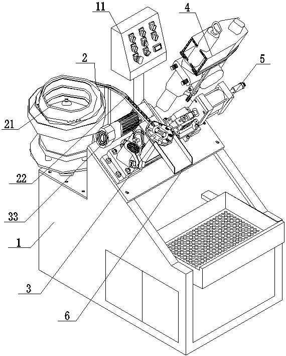
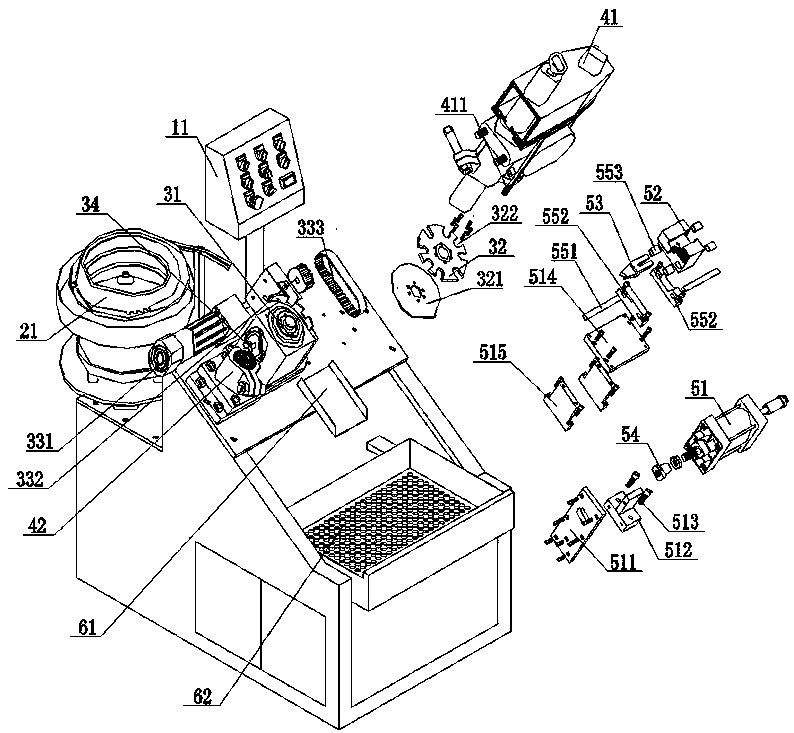
[0020] Such as figure 1 with figure 2 As shown, the present embodiment proposes a fully automatic cap tapping machine, comprising a cabinet 1, a feeding device 2, a driving device 3, a tapping device 4, a compacting device 5 and a discharge device 6, on the cabinet 1 A feeding device 2 is provided, and the feeding device 2 includes a vibrating plate 21 and a sliding track 22, and one end of...


PUM


Abstract

The invention provides a full-automatic cap tapping machine. The full-automatic cap tapping machine comprises a machine box, a feeding device, a driving device, a tapping device and a discharging device, wherein the feeding device is arranged on the machine box and comprises a vibration disc and a sliding rail; the tapping device comprises a tapping bench drill; the driving device comprises a divider and a cap positioning rotary disc; the divider is connected with the cap positioning rotary disc and drives the cap positioning rotary disc to rotate; the vibration disc is connected with one endof the sliding rail, and the other end of the sliding rail is positioned on the divider; a plurality of positioning grooves are formed in the cap positioning rotary disc; the tapping bench drill is arranged above the cap positioning rotary disc; the discharging device is arranged on the lower side of the divider and comprises a sliding way and a water filtering and feeding frame; the sliding way is positioned on the lower side of the divider; and the water filtering and feeding frame is arranged below the sliding way. The full-automatic cap tapping machine is simple in structure, good in machining precision, high in machining efficiency and high in finished product percent of pass.

Description

technical field [0001] The invention relates to the technical field of tapping machines, in particular to a fully automatic cap tapping machine. Background technique [0002] The traditional tapping method is manual operation. Install the tap on the bench drill, and then equip it with a three-jaw tooling fixture. The worker puts the workpiece on the fixture and clamps it to perform tapping action. After tapping, the fixture is released, and then the product is placed in the frame. This kind of tapping method has the following problems: 1. The operation and production efficiency is not high, which often becomes a stuck point in production capacity; 2. Manual operation is fatigued, and it is easy to cause tapping not in place, so that the thread of the supporting product is not completely screwed, resulting in Customer complaints occur; 3. The fixture adopts mechanical locking, which will wear out after a long time. The product will be stuck during the rotation of the tap, wh...

Claims


Application Information

Patent Timeline
IPC IPC(8): B23G1/18B23G1/44B23G11/00B23Q11/00
CPCB23G1/185B23G1/44B23G11/00B23Q11/00
Inventor 吕建攀
Owner 浙江百润厨房用品有限公司
Why Eureka
Try Eureka