Radio frequency identified alignment system and alignment connection method thereof

A radio frequency identification and transmitter technology, applied in the direction of cooperative devices, optics, instruments, etc., can solve the problems of low cost performance, high light source requirements, and high maintenance cost of CCD visual inspection equipment, achieving low cost, low maintenance cost, Easy and quick effect to read

Active Publication Date: 2020-02-14
江苏上达半导体有限公司
View PDF6 Cites 0 Cited by
  • Summary
  • Abstract
  • Description
  • Claims
  • Application Information

AI Technical Summary

Problems solved by technology

[0003] The purchase and maintenance costs of the currently used CCD visual inspection equipment are relatively high, and the cost performance is relatively low, and the CCD visual inspection equipment is an optical processing system, which has high requirements for light sources and is easily affected by external or internal factors such as optical system parameters.

Method used


Image

  • Radio frequency identified alignment system and alignment connection method thereof
  • Radio frequency identified alignment system and alignment connection method thereof

Examples


Embodiment 1

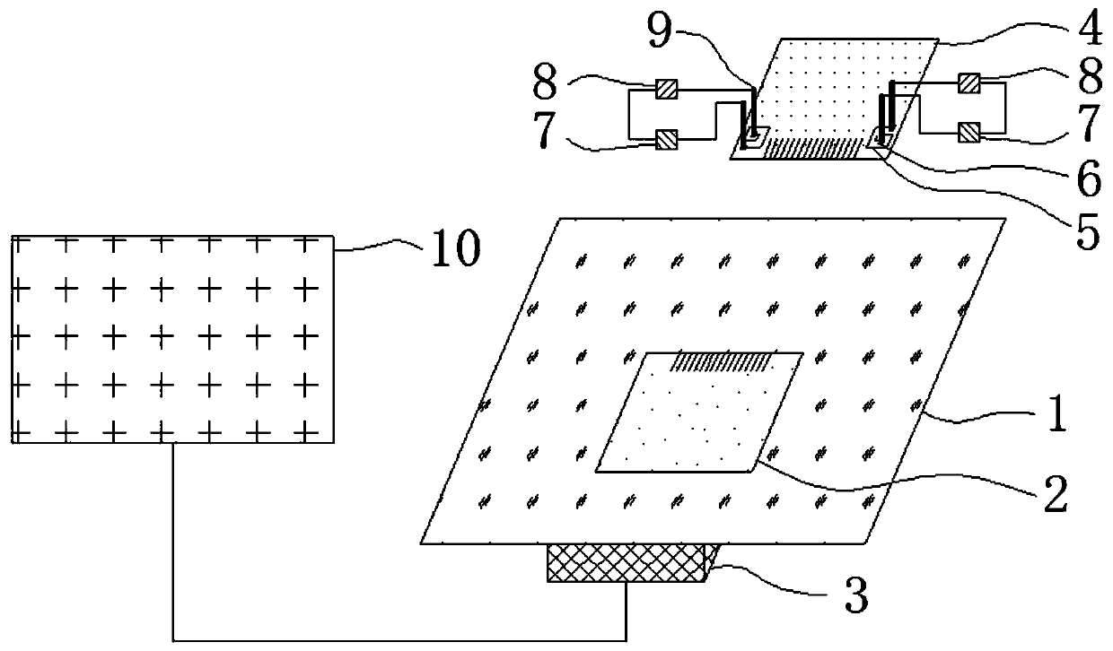
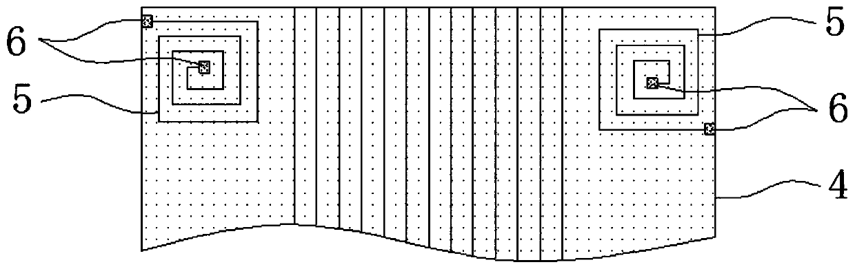
[0031] An alignment system for radio frequency identification, which mainly includes two parts: a signal receiver 3 and a signal transmitter. First, the radio frequency identification signal receiver 3 is fixed on the workbench 1 for receiving electromagnetic waves; then the fingers on the circuit board 4 Both ends are provided with convoluted lines to form the antenna 5 of the signal transmitter, the two ends of the antenna 5 are provided with pads 6, and the probe 9 connecting the chip 7 and the power supply 8 is arranged outside the circuit board 4, and the probe 9 is pressed on the antenna 5. The pad 6 is connected to the antenna 5 to form a signal transmitter;

[0032] The radio frequency identification positioning process is as follows: when the circuit board 4 enters the workbench 1, press the probe 9 on the pad 6 of the antenna 5 to form a complete signal transmitter, and the chip 7 controls the antenna 5 to periodically The signal receiver 3 on the workbench 1 receive...


PUM

PropertyMeasurementUnit
thicknessaaaaaaaaaa
thicknessaaaaaaaaaa
sizeaaaaaaaaaa

Abstract

The invention discloses a radio frequency identified alignment system. The system comprises a worktable, a signal receiver, a computer and a signal emitter; the signal receiver is arranged on the worktable and connected with the computer, and the signal receiver and the signal emitter perform the signal transmission through electromagnetic valve; the signal emitter comprises a circuit board, antennas are arranged at two fingers of the finger on the circuit board, and bonding pads are arranged at two ends of each antenna; probes connected with a chip and a power supply are arranged at outside of the circuit board, and the probes are communicated with the antennas when being pressed on the bonding pads so as to form the signal emitter. Through the system disclosed by the invention, the positioning is performed through the signal transmission by the electromagnetic wave, the reading of the data is independent of a light source, the reading is convenient and quick, and the penetrability communication can be performed.

Description

technical field [0001] The invention relates to an alignment system of radio frequency identification and an alignment connection method thereof. Background technique [0002] In the production process of display modules, electronic components such as driver ICs are generally packaged on circuit boards, and then the circuit boards are bound on the LCD screen. During the binding process, it is necessary to correspond the fingers on the circuit board to the fingers on the display screen one by one, and then perform heat pressing to connect the two for signal transmission. In the traditional method, because it is necessary to connect the fingers of the circuit board and the fingers of the LCD screen one by one, an alignment mark will be set on the LCD screen and the circuit board. During the binding process, on the workbench, Read the Mark images on the circuit board and the LCD screen through the CCD visual inspection equipment, respectively identify the positions of the two ...

Claims


Application Information

Patent Timeline
Patent Type & Authority Applications(China)
IPC IPC(8): G02F1/13G06K17/00
CPCG02F1/1303G06K17/0029
Inventor 方磊王健孙彬沈洪李晓华
Owner 江苏上达半导体有限公司
Why Eureka
Try Eureka