Decorative lamp and luminous jewelry with decorative lamp

A decorative lamp and lampshade technology, which is applied to the parts of lighting devices, semiconductor devices of light-emitting elements, clothing, etc., can solve the problems of low production efficiency, high manufacturing cost, troublesome assembly of light-emitting jewelry, etc., so as to improve production efficiency and simplify the The effect of structure and easy assembly

Active Publication Date: 2020-02-14
艾森(宁波)智能科技有限公司
View PDF6 Cites 3 Cited by
  • Summary
  • Abstract
  • Description
  • Claims
  • Application Information

AI Technical Summary

Problems solved by technology

The above-mentioned decorative lamp for luminous jewelry has the following disadvantages in the actual application process: 1. The lampshade and the lamp cover need to be separately molded and manufactured, and the manufacturing cost is relatively high; 2. After the lampshade and the lamp cover need to be assembled together, Only by fixing the decorative lamp on the jewelry, the assembly of the luminous jewelry is troublesome and the production efficiency is low

Method used


Image

  • Decorative lamp and luminous jewelry with decorative lamp
  • Decorative lamp and luminous jewelry with decorative lamp
  • Decorative lamp and luminous jewelry with decorative lamp

Examples


Embodiment 1

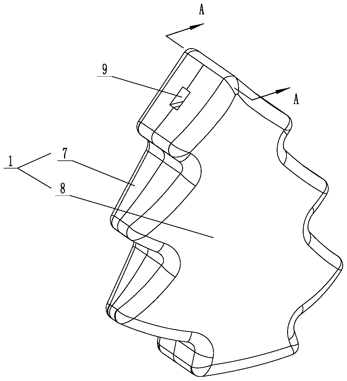
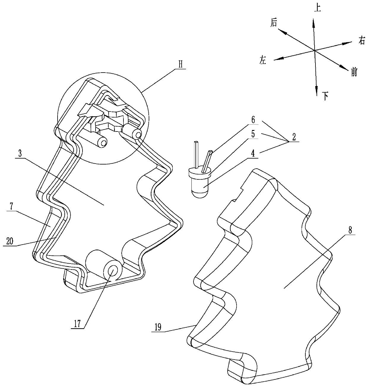
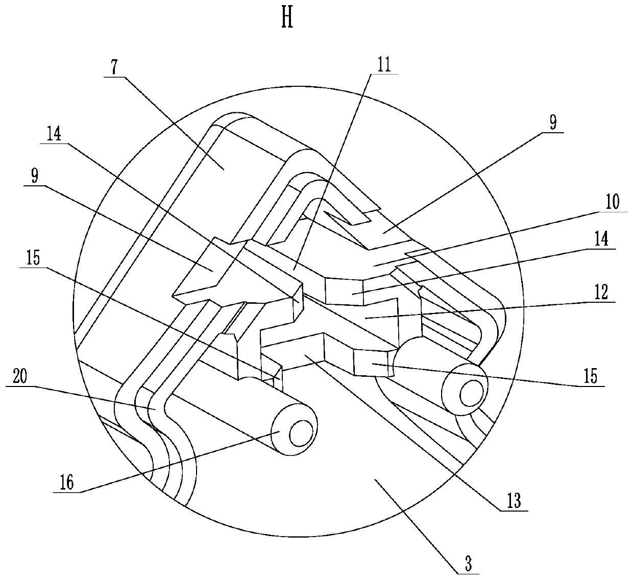
[0044] Such as Figure 1 to Figure 6 As shown, this embodiment discloses a decorative lamp, which includes a lampshade 1 with an inner cavity 3 and an LED lamp bead 2 arranged in the inner cavity 3. The lampshade 1 is provided with two holes for wires 21 to pass through. Threading holes 9, two threading holes 9 communicate with the inner cavity 3, so that one end of the wire 21 can enter the inner cavity 3 and be electrically connected with the LED lamp bead 2; the lampshade 1 is composed of the first cover body 7 and the second cover body 8 The first cover body 7 and the second cover body 8 divide the lampshade 1 and the two threading holes 9 vertically into front and rear parts, and make the two threading holes 9 on the first cover body 7 all look like Groove shape, the inner chamber 3 is also cut into two parts front and back; the two threading holes 9 on the second cover body 8 are all groove-shaped, and the shape of the two threading holes 9 on the second cover body 8 can...

Embodiment 2

[0064] The difference between this embodiment and Embodiment 1 is that the shape of the lampshade 1 is different. In this embodiment, the shape of the lampshade 1 is a cartoon snowflake shape, such as Figure 7 shown.

Embodiment 3

[0066] The difference between this embodiment and Embodiment 1 is that the shape of the lampshade 1 is different. In this embodiment, the shape of the lampshade 1 is a cartoon clover shape, such as Figure 8 shown.

[0067] Embodiments 2 and 3 are to illustrate that the shape of the decorative lamp of the present invention is not fixed, it can be in various shapes, and is not limited to the three shapes listed in Embodiments 1-3.


PUM


Abstract

The invention relates to a decorative lamp. The decorative lamp comprises a lampshade with an inner cavity and an LED lamp bead arranged in the inner cavity; the lampshade is provided with two threading holes for penetrating a wire; the two ends of each threading hole respectively communicate with the inner cavity and the outside of the lampshade; and the lampshade is formed by splicing a first cover body and a second cover body, and the first cover body and the second cover body divide the lampshade vertically into front and rear parts, and two threading holes on the first cover body are through-groove shaped. The invention further relates to a luminous jewelry; the luminous jewelry comprises a battery box, the wire and at least one decorative lamp, and the wire connects the battery box and the decorative lamp in series. The decorative lamp and the luminous jewelry with the decorative lamp provided by the invention have the following advantages that the decorative lamp is simple in structure, low in manufacturing cost, the assembly of the luminous jewelry is convenient, and the production efficiency of luminous jewelry can be improved.

Description

technical field [0001] The invention relates to the technical field of lighting fixtures, in particular to a decorative lamp and luminous jewelry with the decorative lamp. Background technique [0002] Luminous jewelry is mostly used in holiday parties, birthday parties, concerts and other places to increase the atmosphere of the scene. [0003] Existing decorative lights for luminous jewelry generally include a lampshade, LED lamp beads and a lamp cover. The LED lamp beads are arranged in the lamp cover, and a wire groove for accommodating wires is opened on the upper end of the lamp shade, and the lamp cover is connected to the lamp shade and seals the wire groove. , so that the decorative lamp can be hung on the wire, such as the decorative lamp structure disclosed in the authorized announcement number "CN 205807037 U". The above-mentioned decorative lamp for luminous jewelry has the following disadvantages in the actual application process: 1. The lampshade and the lamp...

Claims


Application Information

Patent Timeline
Patent Type & Authority Applications(China)
IPC IPC(8): F21L4/00F21V23/00F21V3/00F21Y115/10F21W121/06
CPCF21L4/00F21V3/00F21V23/002F21W2121/06F21Y2115/10
Inventor 秦燕北
Owner 艾森(宁波)智能科技有限公司
Why Eureka
Try Eureka