Side sealing box sealing machine

A kind of technology of sealing machine and movement, applied in packaging sealing/fastening, external support, transportation packaging, etc., can solve the problems of cumbersome, affecting the appearance of packaging, unstable structure, etc.

Pending Publication Date: 2020-02-14
ZHEJIANG DINGYE MACHINERY
View PDF0 Cites 3 Cited by
  • Summary
  • Abstract
  • Description
  • Claims
  • Application Information

AI Technical Summary

Problems solved by technology

like figure 1 As shown, the left and right cores of the existing side sealing box sealing machine are independent, and the staff need to debug separately. After debugging, it is necessary to check whether the two cores are of the same height. It may affect the aesthetics of the packaging, and even affect the quality of the box sealing; on the other hand, the current side sealing box sealing machine uses the upper and lower middle conveyor belts to clamp and drive the foam box. The conveyor belt has a certain width. A foam box that is too small cannot make the movements on both sides close together and carry out transportation and sealing. For a foam box that is too large, the upper and lower sides of the two outer sides are not well supported, which makes the structure unstable during transportation and affects Sealing quality

Method used


Image

  • Side sealing box sealing machine
  • Side sealing box sealing machine
  • Side sealing box sealing machine

Examples


Embodiment Construction

[0020] Specific embodiments of the present invention will be described in detail below in conjunction with the accompanying drawings.

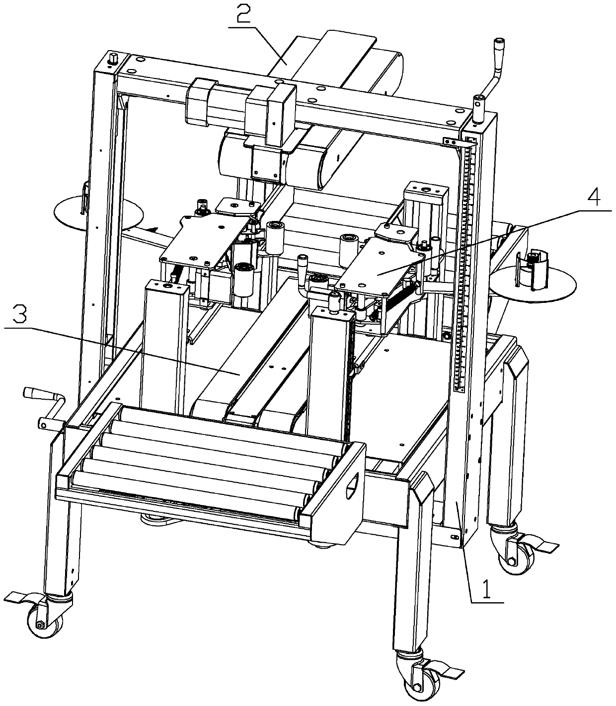
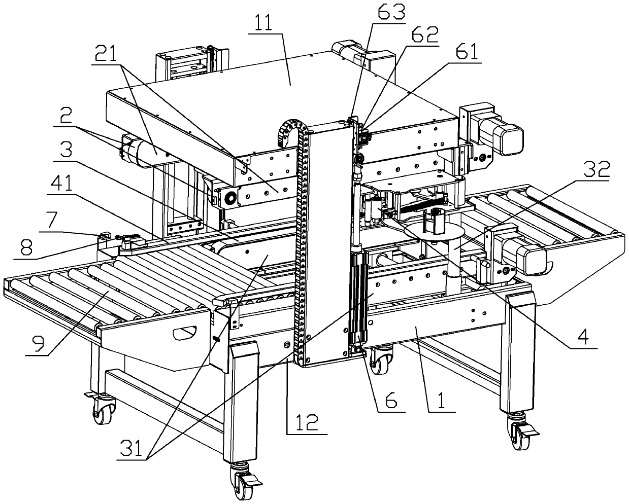
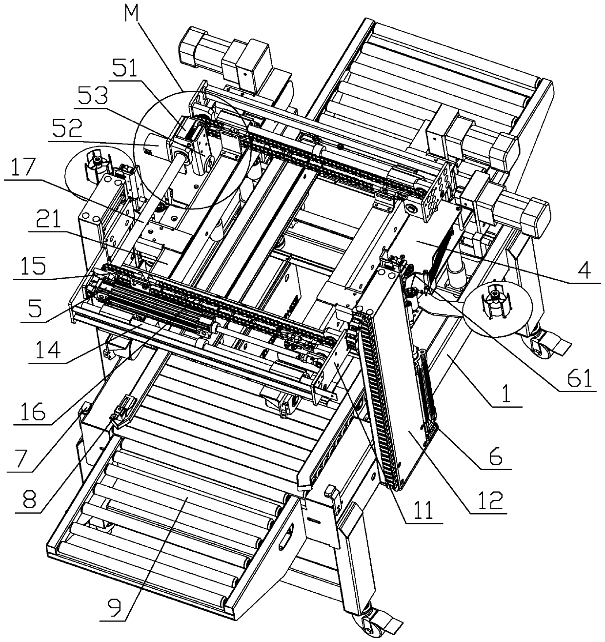
[0021] like figure 2 , 3 , 4, 5, and 6 are specific embodiments of the side sealing box sealing machine of the present invention. This embodiment comprises frame 1, two groups of cores 4, two groups of upper conveyor belts 2, two groups of lower conveyor belts 3, two groups of upper conveyor belts 2 and two groups of lower conveyor belts 3 are arranged correspondingly up and down on the frame 1, Two groups of upper conveyor belts 2 are respectively provided with cores 4 for synchronous activities. The upper conveyor belts 2, lower conveyor belts 3, and cores 4 on both sides are controlled by the first drive mechanism 5 to approach and separate each other in the horizontal direction. The upper conveyor belt 2 and the core 4 are controlled by the second drive mechanism 6 to lift up and down; The core 4 is arranged on an upper support 21, the...


PUM


Abstract

The invention discloses a side sealing box sealing machine. A rack of the side sealing box sealing machine comprises an upper frame and a lower frame. The upper frame is arranged on the lower frame ina vertical sliding manner. Upper conveying belts and machine cores are arranged on upper supports, and lower conveying belts are arranged on lower supports. Vertical shafts are arranged on the lowersupports, and the upper supports can be arranged on the vertical shafts in a vertical sliding manner. Chain wheels are arranged on the two sides of the upper frame, a chain is wound around the chain wheels, and an upper section and a lower section of the chain are connected with the upper supports on the two sides. A second driving mechanism drives the upper supports to ascend and descend on the vertical shafts. When a first driving mechanism drives the upper support on one side to move horizontally, the chain moves clockwise or anticlockwise so as to drive the upper supports on the two sidesto synchronously get close to each other or get away from each other on second transverse shafts, and the lower supports horizontally move synchronously. By means of the side sealing box sealing machine, the upper conveying belts and the machine cores on the two sides can ascend and descend synchronously, and the debugging efficiency is improved; and the upper conveying belts and the lower conveying belts are arranged on the two edges, supporting and conveying can be conducted above and below the two sides, and stability is improved.

Description

technical field [0001] The invention relates to a box sealing machine mechanism, and more specifically relates to a side sealing box sealing machine. Background technique [0002] The carton sealing machine is a device that sticks the tape on the mouth of the carton to complete the packaging. For the packaging and sealing of ordinary cartons, the carton enters the carton sealing machine from one end, and the upper and lower sides of the tape are sealed by the movement set at the top and bottom. Seal the box. Now, for the transportation of fresh fruits and vegetables, foam boxes are used. The foam box and its lid are closed up and down. Therefore, the corresponding box sealing machine adopts the way of setting the movement on the side to seal the box with side tape. like figure 1 As shown, the left and right cores of the existing side sealing box sealing machine are independent, and the staff need to debug separately. After debugging, it is necessary to check whether the tw...

Claims


Application Information

Patent Timeline
IPC IPC(8): B65B51/06
CPCB65B51/06
Inventor 厉勇章加储
Owner ZHEJIANG DINGYE MACHINERY
Why Eureka
Try Eureka