
Visual terminal debugging method and device

A debugging method and terminal technology, which are applied in the fields of telephone communication, electrical components, branch equipment, etc., can solve problems such as low work efficiency and waste of time, and achieve the effect of saving time, improving efficiency and improving debugging efficiency.

Inactive Publication Date: 2011-01-05
QINGDAO HISENSE MOBILE COMM TECH CO LTD
View PDF4 Cites 25 Cited by
  • Summary
  • Abstract
  • Description
  • Claims
  • Application Information

AI Technical Summary

Problems solved by technology

Therefore, in the debugging process, the above-mentioned process needs to be repeated many times, which wastes time and reduces work efficiency

Method used


Image

  • Visual terminal debugging method and device
  • Visual terminal debugging method and device
  • Visual terminal debugging method and device

Examples


Embodiment Construction

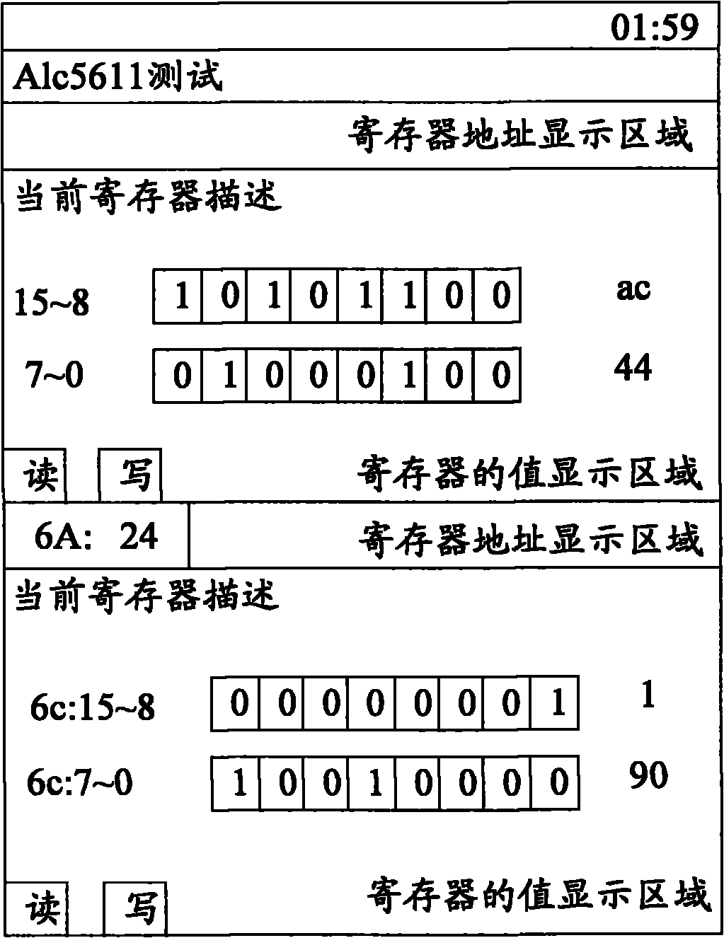
[0017] The embodiment of the present invention provides a visual terminal debugging method, which can directly display the value of the register of the chip to be debugged on the debugging interface, modify it, and directly save the modified register value in the register, which improves the terminal debugging. s efficiency.

[0018] The visualized terminal debugging method provided by the embodiment of the present invention, such as figure 1 shown, including:

[0019] S101. When a debugging instruction is received, a debugging interface is displayed;

[0020] Wherein, the debugging interface may include a register address display area and a register value display area;

[0021] S102. Receive the register address of the chip to be debugged in the mobile terminal input or selected by the user on the debugging interface;

[0022] Such as figure 2 As shown, it is the debugging interface for debugging audio registers. The register address display area displays the address of ...


PUM


Abstract

The invention discloses visual terminal debugging method and device, belonging to the field of mobile phone debugging. The efficiency of terminal debugging can be improved. The method comprises the following steps of: receiving the address of a register of a chip to be debugged in a mobile terminal inputted or selected by a user in a debugging interface, accessing the register according to the address and displaying the value of the register on the debugging interface; and when a command for modifying the value of the register through the debugging interface is received from the user, acquiring the modified value and storing the value in the register. According to the method, the value of the register of the chip to be debugged can be directly displayed on the debugging interface to be modified and the modified value of the register can be directly stored in the register. The efficiency of terminal debugging is improved.

Description

technical field [0001] The invention relates to the field of mobile phone debugging, in particular to a visualized terminal debugging method and device. Background technique [0002] In the existing CDMA and TD mobile phone development process, when debugging the mobile phone, it is generally necessary to import the parameters of the chips that need to be adjusted in the mobile phone to the PC, and use the tools provided by the platform provider to modify the parameters (such as adjusting the parameters of the mobile phone). RF or audio, etc.), to speed up the progress of mobile phone debugging. However, in existing smart phones, multiple chips are used, such as AP chips, Modem chips, Codec chips, etc. In such multi-chip mobile phones, adjustment of a function may require adjustment of parameters in multiple chips. That is, it is necessary to adjust the values ​​of registers in multiple chips. But at present, the tools provided by each chip manufacturer can only adjust the...

Claims


Application Information

Patent Timeline
Patent Type & Authority Applications(China)
IPC IPC(8): H04M1/725H04M1/24H04M1/72403
Inventor 杨鹏王琦孙增国
Owner QINGDAO HISENSE MOBILE COMM TECH CO LTD
Learn More