
Skin graft cutting device

A technology for cutting equipment and skin flaps, which is used in medical science, metal processing, surgery, etc., and can solve the problems of irregular particle size, time-consuming and laborious, and expensive blades.

Pending Publication Date: 2020-02-14
SHANGHAI CHANGHAI HOSPITAL
View PDF0 Cites 1 Cited by
  • Summary
  • Abstract
  • Description
  • Claims
  • Application Information

AI Technical Summary

Problems solved by technology

Mesh skin grafting requires the use of a mesh skin grafting machine, but the distance between the mesh of the mesh skin grafting machine is relatively fixed and cannot be adjusted flexibly according to the wound surface, and the postoperative appearance is not very beautiful
The representative MEEK skin grafting in postage stamp skin grafting requires the use of MEEK skin grafting machine, but the cleaning and disinfection procedures of MEEK skin grafting machine are complicated and require specially trained personnel to operate, and the blades are expensive. If repeated use in clinical practice may cause cross-infection of diseases , In addition, after repeated disinfection and repeated use, the dullness of the blade will affect the cutting effect
Microparticle skin grafting needs to use manual scissors or medical shredders. The manual cutting method is simple and convenient, and does not require special equipment, but it is time-consuming and laborious. It takes at least 2 people to cut for more than 30 minutes to achieve a size of less than 20mm x 20mm. 1mm 2 The preparation standard of particles, and the particle size is very uneven; although the rotary medical peeling machine can quickly prepare particle skins that meet the particle size in a short time, there are also problems of irregular particle size and extremely low particle activity

Method used


Image

  • Skin graft cutting device
  • Skin graft cutting device
  • Skin graft cutting device

Examples


no. 2 example

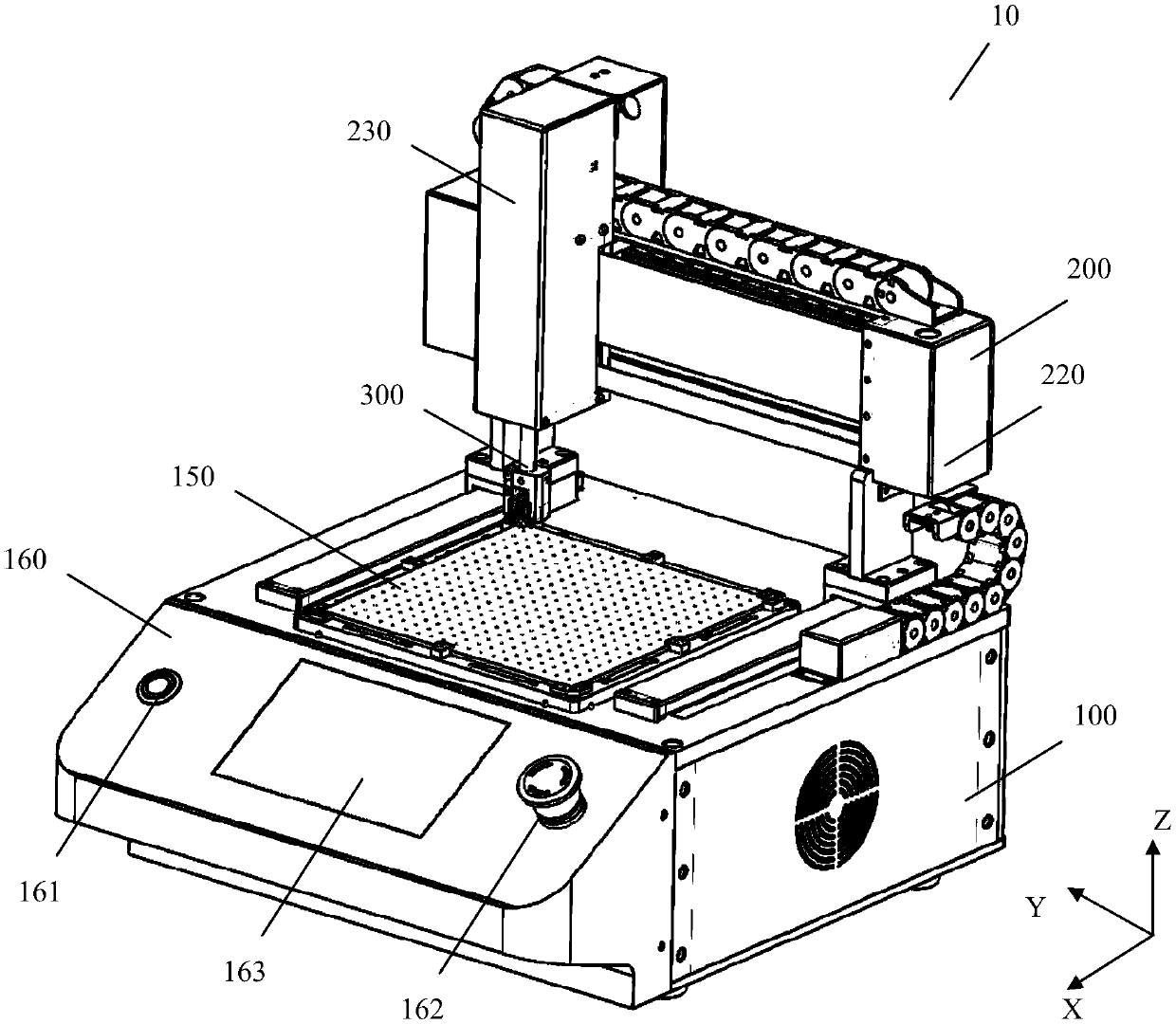
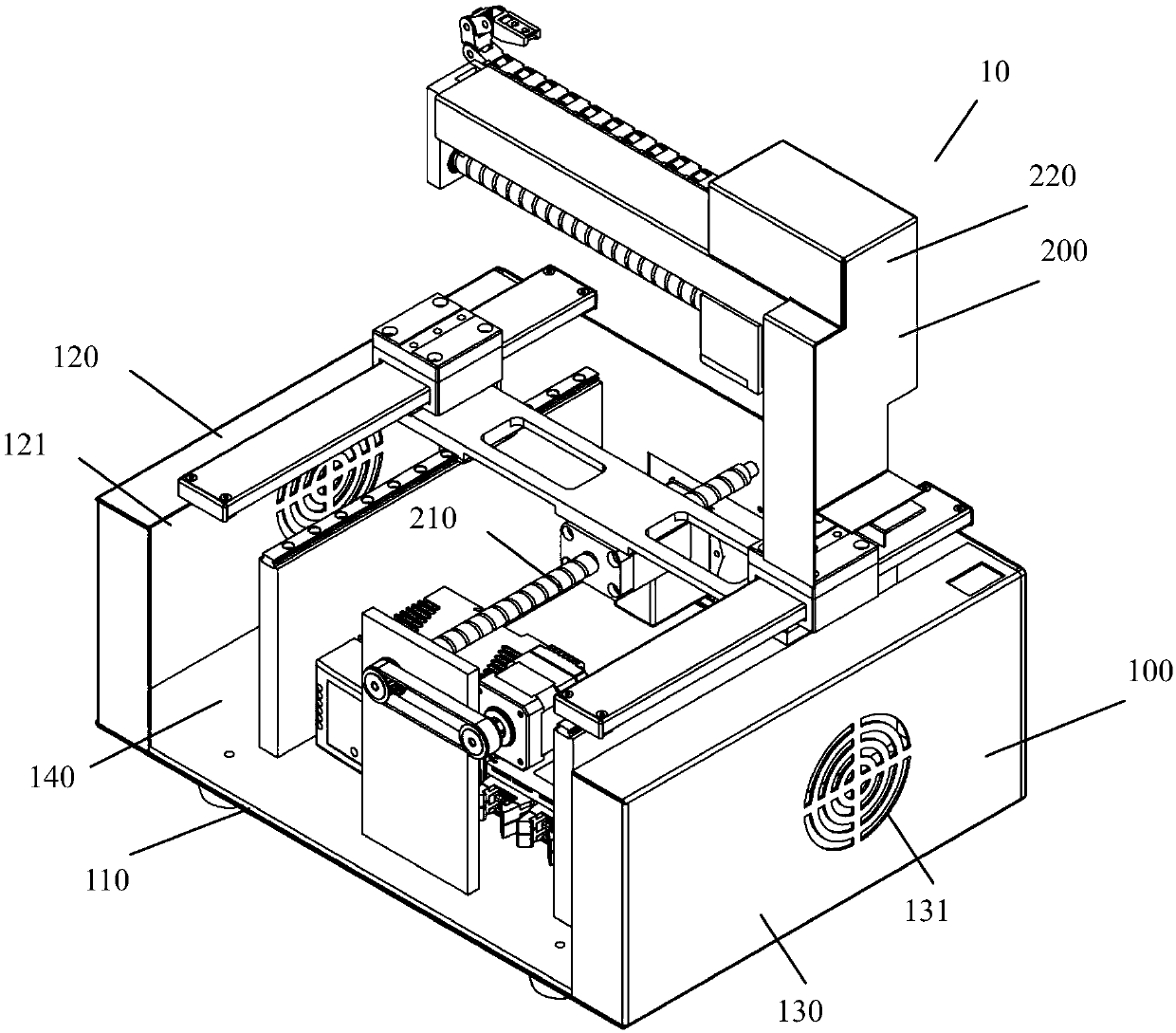
[0081] Figure 9 A flap cutting device 1010 according to a second embodiment of the invention is shown. The flap cutting device 1010 will be referenced by 1000 to indicate the same or similar structures as in the flap cutting device 10 . Same as the skin flap cutting device 10 , the skin flap cutting device 1010 includes a base 1100 , and a three-dimensional moving mechanism 1200 and a skin flap cutting mechanism 1300 located on the base 1100 . The structures of the base 1100 and the skin flap cutting mechanism 1300 are basically the same as those of the base 100 and the flap cutting mechanism 300 in the first embodiment, and the three-dimensional moving mechanism 1200 will be mainly introduced below.

[0082] The three-dimensional moving mechanism 1200 is placed on the base 1100, and is used to move the skin flap cutting mechanism 1300 along the X-axis, Y-axis and Z-axis directions. like Figure 10 As shown, the three-dimensional moving mechanism 1200 includes an X-axis mo...


PUM


Abstract

The invention relates to a skin graft cutting device. The skin graft cutting device comprises a skin graft cutting mechanism, a three-dimensional moving mechanism and a base, wherein the skin graft cutting mechanism cuts a skin into a shape meeting the skin grafting operation requirement; the three-dimensional moving mechanism holds the skin graft cutting mechanism and comprises an X-axis moving assembly, a Y-axis moving assembly and a Z-axis moving assembly, and therefore the skin graft mechanism can be moved in the X, Y and Z-axis directions orthogonal to one another; and the three-dimensional moving mechanism is arranged on the base. The skin graft cutting device is wide in application range, easy and convenient to operate, adjustable in size specification of a pull net and the skin, uniform in particle shape, high in activity retention and particularly suitable for being used in various skin grafting operations.

Description

technical field [0001] The present disclosure generally relates to the field of skin grafting, and in particular relates to a skin graft cutting device. Background technique [0002] At present, the treatment of extremely large and deep burns is still a major challenge for clinicians. Timely wound repair is one of the keys to improving the success rate of treatment. If a patient with a large area of ​​deep burn cannot seal the wound in the early stage, it will bring great difficulties to the follow-up treatment. Therefore, how to use limited skin donor sites to repair large-area deep wounds and ensure the survival rate of grafts is an urgent problem to be solved in the treatment of critically ill burn patients. [0003] Existing skin grafting methods can be divided into mesh skin grafting, postage stamp skin grafting, particle skin grafting, etc. according to the shape of the skin graft, all of which require the use of special equipment for skin graft preparation. Mesh sk...

Claims


Application Information

Patent Timeline
Patent Type & Authority Applications(China)
IPC IPC(8): B26D1/18B26D5/02B26D7/01B26D7/20A61B17/322
CPCB26D1/185B26D5/02B26D7/018B26D7/20A61B17/322B26D7/01B26D1/18
Inventor 肖仕初帅超群夏照帆纪世召郑勇军贲道锋吴琼姜玉
Owner SHANGHAI CHANGHAI HOSPITAL
Learn More