Water spraying type cultivation pond convenient in water changing
A water-spraying, aquaculture pond technology, applied in the field of aquaculture, can solve the problems of single function, difficult to clean fish excrement, blockage of sewer pipes, etc., and achieve the effect of strong function
- Summary
- Abstract
- Description
- Claims
- Application Information
AI Technical Summary
Problems solved by technology
Method used
Image
Examples
Embodiment 1
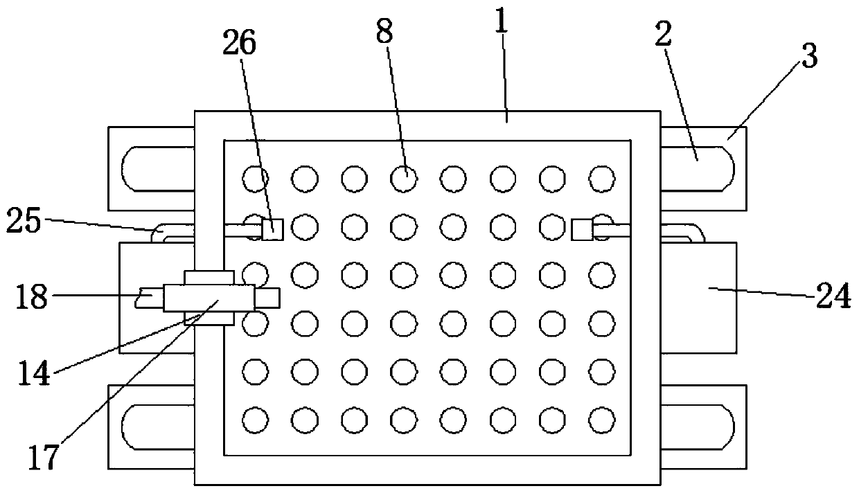
[0022] refer to Figure 1-5 , a water jet culture pond with convenient water exchange, comprising a pool 1, four symmetrically distributed L-shaped support columns 2 are fixedly welded on the side wall of the pool 1, and a flat plate is fixedly welded on the bottom end of the L-shaped support column 2 3. An electric push rod 4 of the same type is fixedly installed on the plate 3, and the top of the electric push rod 4 is fixedly welded with a square groove 6, and the bottom end of the pool 1 is provided with a notch 7, and the top of the square groove 6 is snapped into the notch 7, open the electric push rod 4 to squeeze and connect the square groove 6 with the bottom of the pool 1, and the setting of the notch 7 is also to facilitate the alignment of the clamping position, and the upward and downward movement of the electric push rod 4 is convenient for us to control The position of the square groove 6 is convenient for cleaning the inside of the square groove 6 later.
[00...
Embodiment 2
[0026] refer to image 3 , as another preferred embodiment of the present invention, the difference from Embodiment 1 is that the inside of the square groove 6 is provided with a filter mechanism, and the filter mechanism includes a groove 21 placed inside the square groove 6, and the outer wall of the groove 21 is in line with the square shape The inner wall of the groove 6 fits closely, the inner wall of the groove 21 is positioned at the bottom of the hard plate 11, and the side wall of the square groove 6 is provided with a hole 22, and the inside of the hole 22 is welded with a filter screen 23, when opening the passage at the bottom of the pool 1 , the water flow will flow into the groove 21 through the rubber sealing soft pad 12. At this time, the hard plate 11 has moved down to the stage of offsetting the inner wall of the groove 21, and the water flow can only enter after being filtered by the filter screen 23 in the groove 21. The inside of the square tank 6 is disch...
Embodiment 3
[0028] refer to figure 1 , as another preferred embodiment of the present invention, the difference from Embodiment 1 is that the two sides of the pool 1 are provided with ventilation mechanisms, and the ventilation mechanisms include an air pump 24 fixedly installed on the side wall of the pool 1 and an air pump 24 fixedly installed on the side wall of the pool. 1 The trachea 25 inside the side wall, one end of the trachea 25 is fixedly connected with the air outlet of the air pump 24, the other end of the trachea 25 is fixedly connected with an air stone 26, a sealing plug 27 is arranged between the trachea 25 and the side wall of the pool 1, and the ventilation The setting of the mechanism can solve the problem of complicated winding of the ventilation tube before.
PUM
 Abstract
Description
Claims
Application Information
 - R&D
- Intellectual Property
- Life Sciences
- Materials
- Tech Scout
- Unparalleled Data Quality
- Higher Quality Content
- 60% Fewer Hallucinations
Browse by: Latest US Patents, China's latest patents, Technical Efficacy Thesaurus, Application Domain, Technology Topic, Popular Technical Reports.
© 2025 PatSnap. All rights reserved.Legal|Privacy policy|Modern Slavery Act Transparency Statement|Sitemap|About US| Contact US: help@patsnap.com


