
Physical free fall experiment simulation device

A free fall, experimental simulation technology, applied in teaching models, educational appliances, instruments, etc., can solve the problems of complex structure, troublesome users, difficult to guarantee balance, etc., and achieve strong experimental design and high measurement accuracy. , the effect of strong design

Inactive Publication Date: 2020-02-11
周宇航
View PDF6 Cites 0 Cited by
  • Summary
  • Abstract
  • Description
  • Claims
  • Application Information

AI Technical Summary

Problems solved by technology

[0002] In the teaching process of middle school physics, in order for students to better and more intuitively understand the acceleration data, it is necessary to demonstrate the simulated free fall movement to students. In the free fall experiment, special equipment is needed to support it, but the traditional free fall experiment simulation device exists. Many problems, complex structure, inconvenient use and adjustment, insufficient fixation, and difficult to guarantee the balance, resulting in the accuracy of the simulation test to be questioned, which brought great trouble to the user, and it is impossible to adjust the landing ground according to the demand. Adjustment of the horizontal angle with the placement surface makes it difficult to adjust the height of the falling point, the accuracy of the experimental data is difficult to be guaranteed, it is not convenient to release the falling ball, the timing is not accurate enough, and the cut-off time lags behind when touching the ground, which virtually increases the teacher's teaching The burden reduces the accuracy of the simulation test, resulting in low efficiency of the free fall experiment simulator, so it is imperative to realize a high school physics free fall experiment simulator that can solve such problems

Method used


Image

  • Physical free fall experiment simulation device
  • Physical free fall experiment simulation device
  • Physical free fall experiment simulation device

Examples


Embodiment Construction

[0022] In order to further understand the content, features and effects of the present invention, the following examples are given, and detailed descriptions are given below with reference to the accompanying drawings.

[0023] The structure of the present invention will be described in detail below in conjunction with the accompanying drawings.

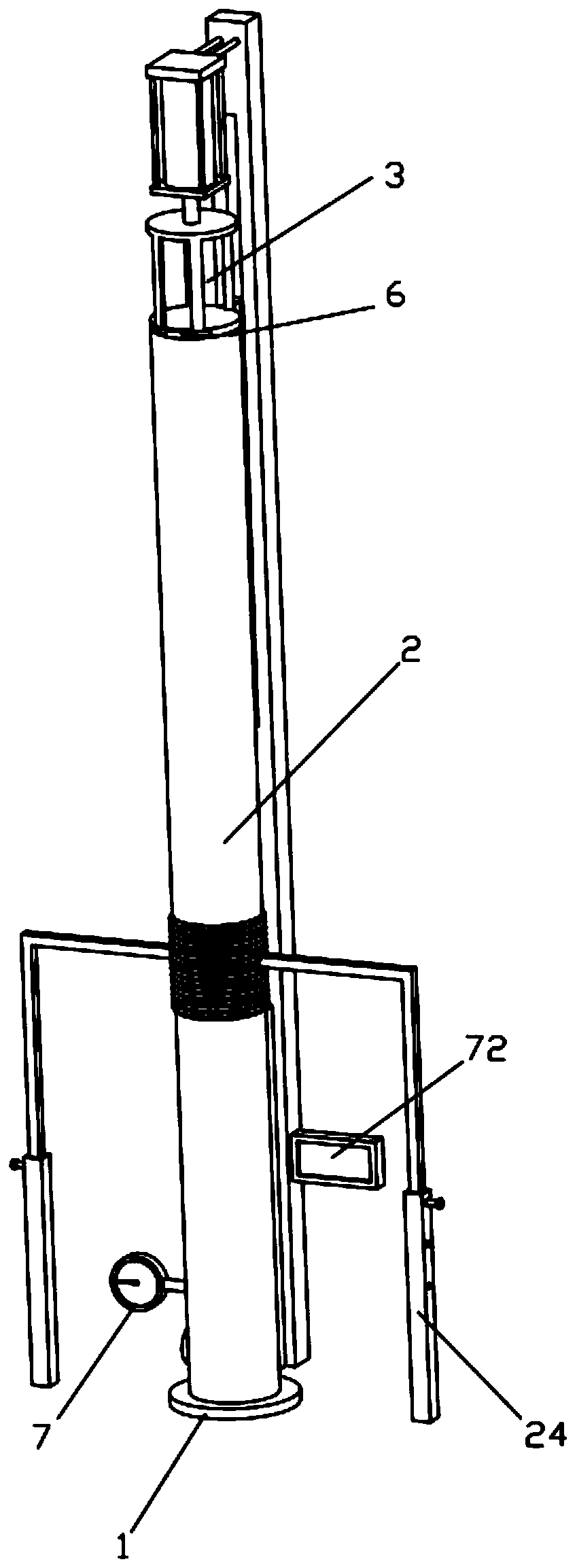
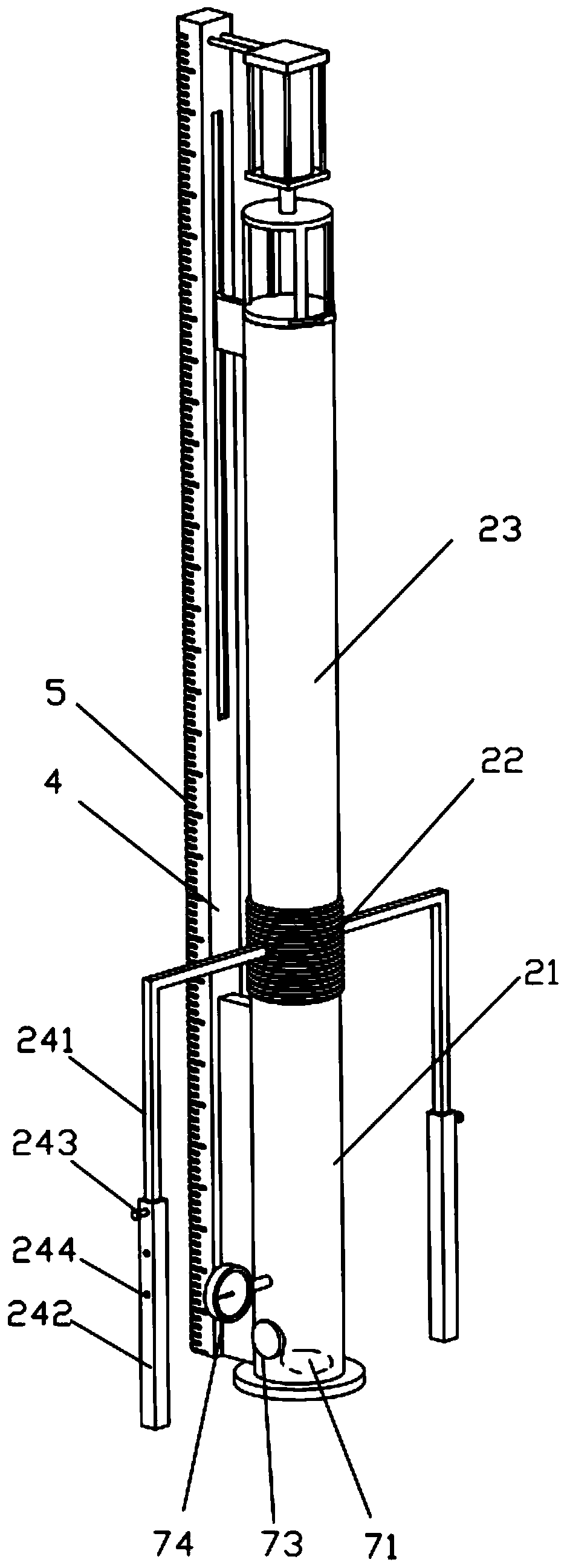
[0024] like Figure 1 to Figure 4 As shown, the physical free fall experiment simulation device provided by the embodiment of the present invention includes a placement base 1, a vacuum pipeline assembly 2 is fixed on the upper end of the placement base 1, and a clamping and fixing assembly is fixed on the upper end of the vacuum pipeline assembly 2 3. A reference rod 4 is fixed on the outer wall of the vacuum pipeline assembly 2, and a scale 5 is provided on the reference rod 4 along the height direction of the reference rod 4. The clamping and fixing assembly 3 is provided near the end of the vacuum pipeline assembly 2. The connec...


PUM


Abstract

The invention belongs to the technical field of experimental equipment and discloses a physical free fall experiment simulation device. The device comprises a carrying base, wherein a vacuum pipelinecomponent is fixed to the upper end of the carrying base, a clamping fixing component is fixed to the upper end of the vacuum pipeline component, a reference rod is fixed to the outer wall of the vacuum pipeline component, scale lines are arranged on the reference rod in the height direction of the reference rod, a connecting piece is arranged at the end, close to a vacuum pipeline, of the clamping fixing component, and a measurement component is arranged inside the vacuum pipeline component. Through the vacuum pipeline component, the vertical height of an extension pipe can be adjusted, freefall experiments at different heights can be performed, the designability is strong, adjustment pieces are fixed to the two sides of the extension pipe at the same time, and the device is simple in structure and convenient to adjust; and meanwhile, an air extraction opening is formed in the bottom of a fixed pipe, air extraction can be performed through the air extraction opening, the interior ofthe vacuum pipeline is in a vacuum state, the free fall experiments in the vacuum state and a normal air pressure state can be performed simultaneously, variables are controllable, and the designability of the experiments is strong.

Description

technical field [0001] The invention belongs to the technical field of experimental equipment, and in particular relates to a physical free-fall experiment simulation device. Background technique [0002] In the teaching process of middle school physics, in order for students to better and more intuitively understand the acceleration data, it is necessary to demonstrate the simulated free fall movement to students. In the free fall experiment, special equipment is needed to support it, but the traditional free fall experiment simulation device exists. Many problems, complex structure, inconvenient use and adjustment, insufficient fixation, and difficult to guarantee the balance, resulting in the accuracy of the simulation test to be questioned, which brought great trouble to the user, and it is impossible to adjust the landing ground according to the demand. Adjustment of the horizontal angle with the placement surface makes it difficult to adjust the height of the falling p...

Claims


Application Information

Patent Timeline
Patent Type & Authority Applications(China)
IPC IPC(8): G09B23/10
CPCG09B23/10
Inventor 周宇航
Owner 周宇航
Learn More