
Portable multifunctional optical cable welding box

A multi-functional and portable technology, applied in the direction of light guide, optics, optical components, etc., can solve the problems of cumbersome optical cable welding platform, no unified storage device, and increase the difficulty of finding, so as to reduce the difficulty of handling and work intensity, and save materials. time, saving pick-and-place time

Pending Publication Date: 2020-02-11
STATE GRID ZHEJIANG LINAN POWER SUPPLY
View PDF0 Cites 0 Cited by
  • Summary
  • Abstract
  • Description
  • Claims
  • Application Information

AI Technical Summary

Problems solved by technology

[0002] Optical cable fusion is an important part of field optical cable work. In infrastructure projects, relocation work, technical overhaul, and rapid fault handling, optical cable fusion operations will be involved. Optical cable fusion is a delicate job. The working environment and working tools The requirements are high. Therefore, the storage of optical cable melting tools requires sealing, moisture-proof, and dust-proof. The platform for optical cable work is required to be firm and stable. At present, the optical cable working platform and the optical cable welding tools are carried separately, and there is no unified storage device, which increases the difficulty of finding, and easily causes the loss of tools, which reduces the operation efficiency, and the currently used optical cable welding platform is heavy and difficult to carry. , increasing the difficulty of handling

Method used


Image

  • Portable multifunctional optical cable welding box
  • Portable multifunctional optical cable welding box
  • Portable multifunctional optical cable welding box

Examples


Embodiment

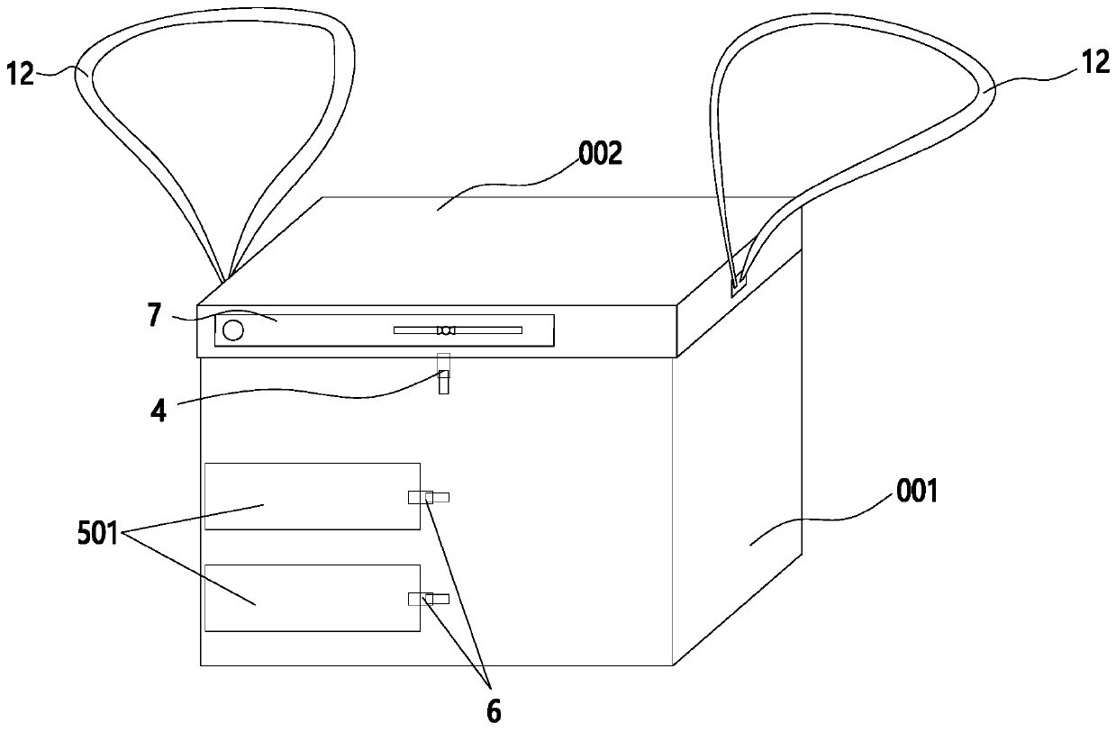
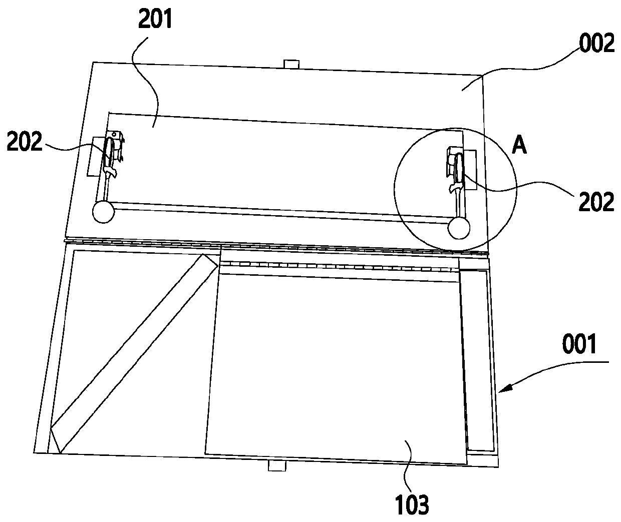
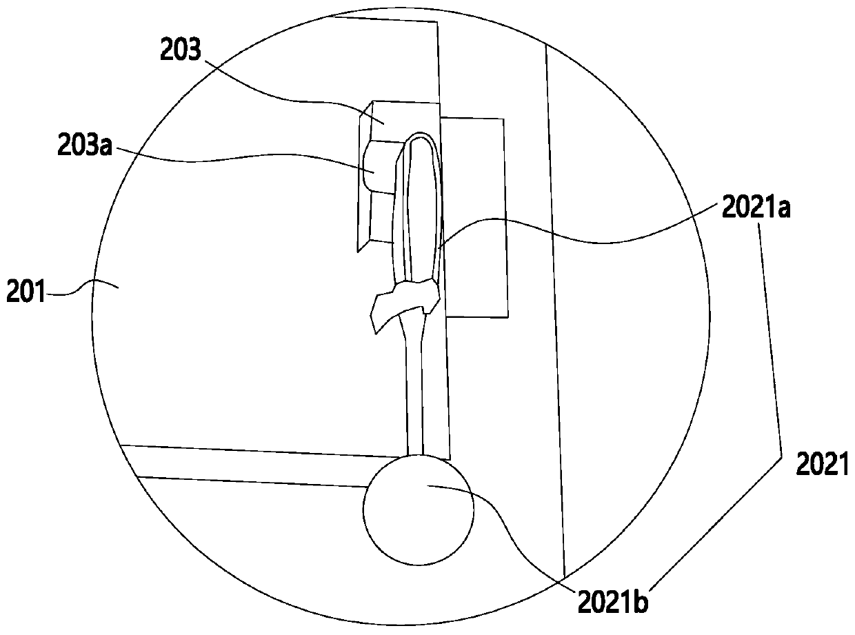
[0034] Such as Figure 1 to Figure 7 As shown, a portable multifunctional optical cable fusion splicing box includes a lower box body 001 and a box cover 002 hinged on the lower box body 001. A first operating platform 201 is provided on the inside of the box cover 002, and the two ends of the first operating platform 201 are provided with There is an optical cable clamping mechanism 202, and the lower box body 001 is provided with an accommodation cavity 101 for accommodating the optical cable welding machine. The opening of the accommodation cavity 101 is upward, and a movable cover 103 is hinged above the accommodation cavity 101, and the movable cover 103 forms a second operating platform. When placing the optical cable fusion splicer, open the movable cover 103 and put it into the accommodation cavity 101. The fusion splicing box includes the storage mode in which the box cover 002 is closed on the lower box body 001 and the use mode after the box cover 002 is opened. In ...


PUM


Abstract

The invention discloses a portable multifunctional optical cable welding box, and belongs to the field of optical fiber communication. The portable multifunctional optical cable welding box comprisesa lower box body and a box cover hinged to the lower box body. The inner side of the box cover is provided with a first operation platform for placing an optical cable connector box. Two ends of the first operation platform are provided with optical cable clamping mechanisms. An accommodating cavity for accommodating an optical cable fusion splicer is formed in the lower box body. A movable coverplate is hinged above the accommodating cavity. The movable cover plate forms a second operation platform. The welding box has a storage mode that the box cover covers the lower box body and a use mode that the box cover is opened. In the storage mode, the optical cable fusion splicer is stored in the accommodating cavity, in the use mode, the optical cable connector box is placed on the first operation platform, the optical cable fusion splicer is placed on the second operation platform, the number and the weight of carried objects are reduced, time and labor are saved, the carrying difficulty is lowered, and the carrying difficulty and the working intensity of operators are lowered.

Description

【Technical field】 [0001] The invention relates to the field of optical fiber communication, in particular to a portable multifunctional optical cable fusion splicing box. 【Background technique】 [0002] Optical cable fusion is an important part of field optical cable work. In infrastructure projects, relocation work, technical overhaul, and rapid fault handling, optical cable fusion operations will be involved. Optical cable fusion is a delicate job. The working environment and working tools The requirements are high. Therefore, the storage of optical cable melting tools requires sealing, moisture-proof, and dust-proof. The platform for optical cable work is required to be firm and stable. At present, the optical cable working platform and the optical cable welding tools are carried separately, and there is no unified storage device, which increases the difficulty of finding, and easily causes the loss of tools, which reduces the operation efficiency, and the currently used ...

Claims


Application Information

Patent Timeline
IPC IPC(8): G02B6/255
CPCG02B6/2551
Inventor 王均健张攀陈礼朝吕华郭谡杨巍许峰毛江东许江颖沈哲清胡永昌王成峰彭斌林青山姚晓倩
Owner STATE GRID ZHEJIANG LINAN POWER SUPPLY
Learn More