
Platform device and flatness detection and adjustment equipment

A carrier platform and bearing surface technology, applied in the direction of measuring devices, optical devices, instruments, etc., can solve problems such as difficulty in ensuring flatness, unfavorable target operation, and target warping

Inactive Publication Date: 2020-02-11
UTECHZONE CO LTD
View PDF9 Cites 1 Cited by
  • Summary
  • Abstract
  • Description
  • Claims
  • Application Information

AI Technical Summary

Problems solved by technology

However, the solution of positioning the target on the stage under local force may easily cause the target to warp and make it difficult to ensure its flatness, which is not conducive to subsequent operations on the target

Method used


Image

  • Platform device and flatness detection and adjustment equipment
  • Platform device and flatness detection and adjustment equipment
  • Platform device and flatness detection and adjustment equipment

Examples


Embodiment Construction

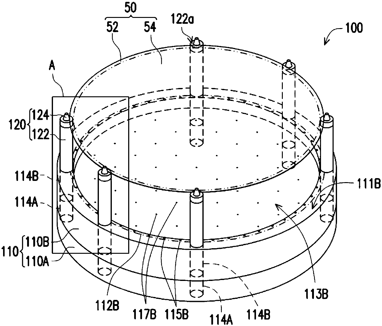
[0041] For clarity and ease of explanation, the figure 1 , Figure 2A , Figure 2B as well as Figure 2C The first through hole 114A of the first seat portion 110A and the second through hole 114B of the second seat portion 110B are shown in dashed lines. exist figure 1 , Figure 2A as well as Figure 2B The boundary of the adsorption region 112B of the second seat portion 110B on the first bearing surface 111B is shown by a dot chain line. exist Figure 2A , Figure 2B as well as Figure 2C The dotted line shows the structure behind the target 50 , and the boundary between the outer edge portion 52 and the middle portion 54 of the target 50 is shown by a chain line of two dots.

[0042] Please refer to figure 1 , the stage device 100 includes a base 110 assembled and fixed by the first seat part 110A and the second seat part 110B (for example, assembled and fixed by screws), and is used to carry such as Figure 2A Lift assembly 120 of target 50 is shown. The shape...


PUM


Abstract

The invention provides a platform device and a flatness detection and adjustment device. The platform device includes a base, an adsorption area, and an air floating area. The base has a first bearingsurface to carry a target. The adsorption area is arranged on the first bearing surface, so that the target is adsorbed on the first bearing surface. The air floating area is adjacent to the adsorption area and is recessed on the first bearing surface. When the first bearing surface carries the target, the target covers the adsorption area and the air floating area. The suction area provides suction to the outer edge portion of the target, and the air-float area provides blowing force to the middle portion within the outer edge portion of the target.

Description

technical field [0001] The invention relates to a stage device and a flatness detection and adjustment device, in particular to a stage device and a flatness detection and adjustment device for increasing the flatness of a carried target object. Background technique [0002] Generally speaking, the stage can be used to carry a target object (such as a substrate such as a glass substrate) to facilitate subsequent operations on the target object (such as inspection or processing operations on the target object). In order to avoid damage caused by the direct contact of the target object with the stage, one of the current solutions is to reduce the contact between the target object and the stage, for example, to place part of the target object on the stage, and to force the part of the object to Positioned on the carrier, thereby reducing the damage caused by the target object contacting the carrier. However, the solution of positioning the target on the carrier under local for...

Claims


Application Information

Patent Timeline
IPC IPC(8): G01B11/30
CPCG01B11/30
Inventor 邹嘉骏赖宪平
Owner UTECHZONE CO LTD
Learn More