
Machine room ventilation structure

A technology of machine room and baffle structure, which is applied in the direction of cooling/ventilation/heating transformation, electrical equipment construction parts, electrical components, etc., which can solve the problems of difficult temperature control and large energy loss in aging machine rooms, and reduce energy loss. Improve the utilization rate and achieve the effect of heat dissipation and cooling

Pending Publication Date: 2020-02-07
INSPUR SUZHOU INTELLIGENT TECH CO LTD
View PDF0 Cites 0 Cited by
  • Summary
  • Abstract
  • Description
  • Claims
  • Application Information

AI Technical Summary

Problems solved by technology

Among them, the temperature control of the aging computer room is particularly difficult, and more power resources are needed to cool down the servers in the computer room, resulting in a large energy loss.

Method used


Image

  • Machine room ventilation structure
  • Machine room ventilation structure
  • Machine room ventilation structure

Examples


Embodiment Construction

[0028] The invention discloses a ventilation structure for a machine room to reduce energy loss.

[0029] The following will clearly and completely describe the technical solutions in the embodiments of the present invention with reference to the accompanying drawings in the embodiments of the present invention. Obviously, the described embodiments are only some, not all, embodiments of the present invention. Based on the embodiments of the present invention, all other embodiments obtained by persons of ordinary skill in the art without making creative efforts belong to the protection scope of the present invention.

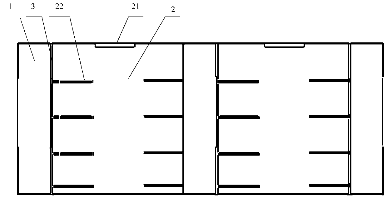
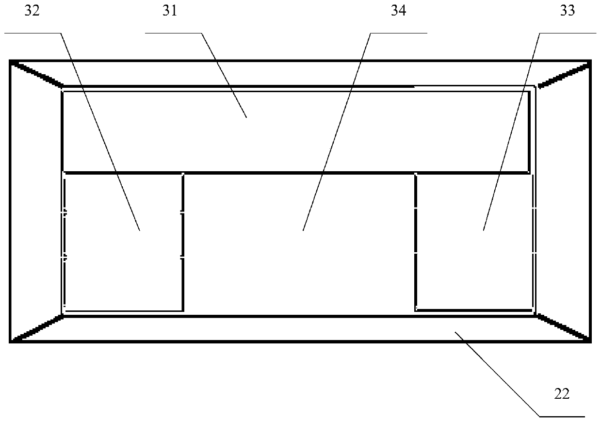
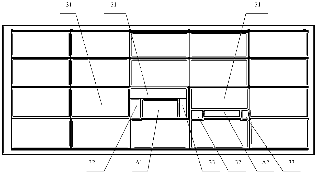
[0030] Please refer to Figure 1-Figure 4 , the embodiment of the present invention provides a ventilation structure for a machine room, including a machine room 2 , a hot aisle 1 and a baffle structure 3 . The server A is used to be installed in the computer room 2, and the computer room 2 has a cold air supply structure 21; the hot aisle 1 is used to connect w...


PUM


Abstract

The invention provides a machine room ventilation structure. The machine room ventilation structure comprises: a machine room; a server arranged in the machine room, wherein the machine room has a cool air supply structure; a heat channel used for connecting with the heat dissipation opening of the server; and a baffle structure used for separating the machine room from the heat channel, wherein athrough hole structure communicating with the machine room and the heat channel is formed in the baffle structure, the through hole structure is used for communicating with the heat dissipation opening of the server, and the inner wall of the through hole structure is attached to the outer wall of the server. According to the machine room ventilation structure, cool air only can pass through theserver, cools parts in the server, passes through the heat dissipation opening of the server and the through hole structure of the baffle structure and flows into the heat channel so as to effectivelyachieve heat dissipation and cooling of the server, avoid the loss caused by directly flowing the cool air into the heat channel, improve the utilization of the cool air, reduce the loss of the energy and have an effect on energy saving and consumption reduction.

Description

technical field [0001] The invention relates to the technical field of heat dissipation equipment, in particular to a ventilation structure for a machine room. Background technique [0002] For the server room, it is very important to ensure that the temperature of the computer room is within a reasonable range. Enterprises will spend a lot of power resources on air conditioning and cooling to ensure the temperature of the computer room. Among them, the temperature control of the aging computer room is particularly difficult, and more power resources are needed to cool down the servers in the computer room, resulting in a large energy loss. [0003] Therefore, how to reduce energy loss is very important. Contents of the invention [0004] In view of this, the present invention provides a ventilation structure for a machine room to reduce energy loss. [0005] A ventilation structure for a machine room, comprising: [0006] A computer room, the server is configured to be...

Claims


Application Information

Patent Timeline
Patent Type & Authority Applications(China)
IPC IPC(8): H05K7/20
CPCH05K7/20718
Inventor 牟明智
Owner INSPUR SUZHOU INTELLIGENT TECH CO LTD
Learn More