
Optical fiber dedicated channel online monitoring device and monitoring method thereof

A technology dedicated to optical fiber and monitoring device, applied in electromagnetic wave transmission systems, electrical components, transmission systems, etc., can solve the problems of distinguishing fault intervals, waste of manpower and material resources, etc., and achieve the effects of stable operation, simple installation, simple and reliable principle

Pending Publication Date: 2020-02-07
YANTAI POWER SUPPLY COMPANY OF STATE GRID SHANDONG ELECTRIC POWER
View PDF3 Cites 3 Cited by
  • Summary
  • Abstract
  • Description
  • Claims
  • Application Information

AI Technical Summary

Problems solved by technology

At present, there is no technology for channel abnormal defects to distinguish fault areas remotely, and maintenance and ICT professionals need to send personnel to the scene to deal with them as soon as possible. The average time is 2 hours per person, wasting 50% or more of manpower and material resources

Method used


Image

  • Optical fiber dedicated channel online monitoring device and monitoring method thereof
  • Optical fiber dedicated channel online monitoring device and monitoring method thereof
  • Optical fiber dedicated channel online monitoring device and monitoring method thereof

Examples


Embodiment 1

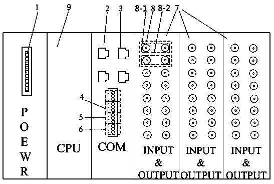
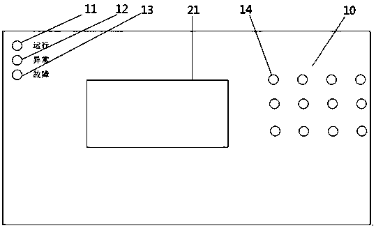
[0024] For an online monitoring device for a dedicated optical fiber channel in this embodiment, please refer to Figure 1-3 , including a CPU9 installed in the casing 10, the CPU9 is connected to a power board 1, a communication board 2, and the communication board 2 is provided with four Ethernet ports 3 for realizing communication of the 103 protocol and the 61850 protocol in the station, and the communication board 2 is also provided with There are two groups of 485 connection ports 4, and two groups of 485 connection ports 4 can communicate with the line protection with a special channel for optical fiber, and communicate with the protection information substation. The communication board 2 is also provided with a time synchronization device for supporting the electrical B code. The B code timing connection port 5, the communication board 2 is also provided with a printer connection port 6, the communication board 2 is also connected with three optical fiber interface boar...

Embodiment 2

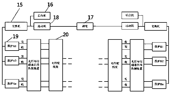
[0028] For the monitoring method of an online monitoring device for a dedicated optical fiber channel in this embodiment, refer to the attached Figure 1-3 , through the optical fiber dedicated channel on-line monitoring device to connect all the running lines in the station longitudinal differential protection device 19 dedicated optical fiber "receive" and "send" signals, monitor and forward them, and the forwarded optical fiber signals are connected to the optical fiber distribution frame 20 After the signal processing, it is transmitted to the opposite side of the line following the primary line. After the signal processing is also performed on the opposite side, it passes through the optical fiber distribution frame on the opposite side and is connected to the on-line monitoring device for the dedicated fiber channel on the opposite side. The on-line monitoring device for the dedicated fiber channel forwards After monitoring the power signal in the optical fiber, the optic...


PUM


Abstract

The invention relates to a line longitudinal differential protection dedicated optical fiber channe on-line monitoring device, which is widely applied to signal monitoring of a special optical fiber channel for line main protection of 110kV and above voltage classes, and belongs to the technical field of power transformation maintenance sites. The device comprises a CPU installed in a shell. The CPU is connected with a power supply board and a communication board; the communication board is provided with four Ethernet ports used for supporting 103 protocol and 61850 protocol communication in astation. The communication board is also provided with two groups of 485 wiring ports. The two groups of 485 wiring ports can be in protection communication with a line with an optical fiber specialchannel and in communication with a protection information substation; the communication board is also provided with a B code time synchronization wiring port used for supporting electric B code timesynchronization. The communication board is also provided with a printer wiring port, the communication board is also connected with three optical fiber interface boards, each optical fiber interfaceboard is provided with four groups of optical fiber input and output interfaces, each optical fiber input and output interface comprises four optical fiber interface, the upper two ports are longitudinal differential protection dedicated optical fiber channel interfaces, and the lower two ports are optical fiber distribution frame optical fiber interfaces. The device is simple and reliable in principle, easy and convenient to install, stable in operation, wide in application range and capable of shortening defect elimination time and remotely positioning a fault area in real time.

Description

technical field [0001] The invention relates to an online monitoring device for an optical fiber channel dedicated to line longitudinal differential protection, which is widely used in the signal monitoring of an optical fiber channel dedicated to line main protection at a voltage level of 110kV and above, and belongs to the field technical field of substation maintenance. Background technique [0002] The longitudinal differential protection is the main protection of the 110kV and above line protection. Its principle is to use the dedicated fiber optic channel to transmit the secondary current on both sides of the line, and compare and calculate it to determine whether there is an internal fault. If the dedicated optical fiber channel is abnormal, the longitudinal differential protection will be out of operation, and the line protection will lose its main protection. Its sensitivity and quick disconnection to grounding, short circuit and other defects will be significantly r...

Claims


Application Information

Patent Timeline
Patent Type & Authority Applications(China)
IPC IPC(8): H04B10/079
CPCH04B10/0791
Inventor 周志娟王洪光初嘉伟徐军白皓郭茗菘唐鑫范晨飞王新迟杰孟庭如唐文举刘虎
Owner YANTAI POWER SUPPLY COMPANY OF STATE GRID SHANDONG ELECTRIC POWER
Learn More