
Lens structure, lens antenna and electronic equipment

A technology of lens structure and lens antenna, which is applied in the direction of antenna, antenna array, antenna support/installation device, etc., can solve the problems of reducing the efficiency of lens antenna and electromagnetic wave loss, etc., and achieve the effect of small loss, low cost and large bandwidth

Active Publication Date: 2020-02-07
GUANGDONG OPPO MOBILE TELECOMM CORP LTD
View PDF12 Cites 1 Cited by
  • Summary
  • Abstract
  • Description
  • Claims
  • Application Information

AI Technical Summary

Problems solved by technology

Since the electromagnetic wave enters the lens, it generally needs to pass through multiple dielectric layers, and the introduction of the medium will cause the loss of the electromagnetic wave, thereby reducing the efficiency of the lens antenna.

Method used


Image

  • Lens structure, lens antenna and electronic equipment
  • Lens structure, lens antenna and electronic equipment
  • Lens structure, lens antenna and electronic equipment

Examples


Embodiment Construction

[0037] In order to facilitate the understanding of the present application, the present application will be described more fully below with reference to the relevant drawings. Preferred embodiments of the application are shown in the accompanying drawings. However, the present application can be embodied in many different forms and is not limited to the embodiments described herein. On the contrary, the purpose of providing these embodiments is to make the understanding of the disclosure of the application more thorough and comprehensive.

[0038] It can be understood that the terms "first", "second" and the like used in this application may be used to describe various elements herein, but these elements are not limited by these terms. These terms are only used to distinguish a first element from another element, and should not be interpreted as indicating or implying relative importance or implying the number of technical features indicated. Thus, the features defined as "f...


PUM


Abstract

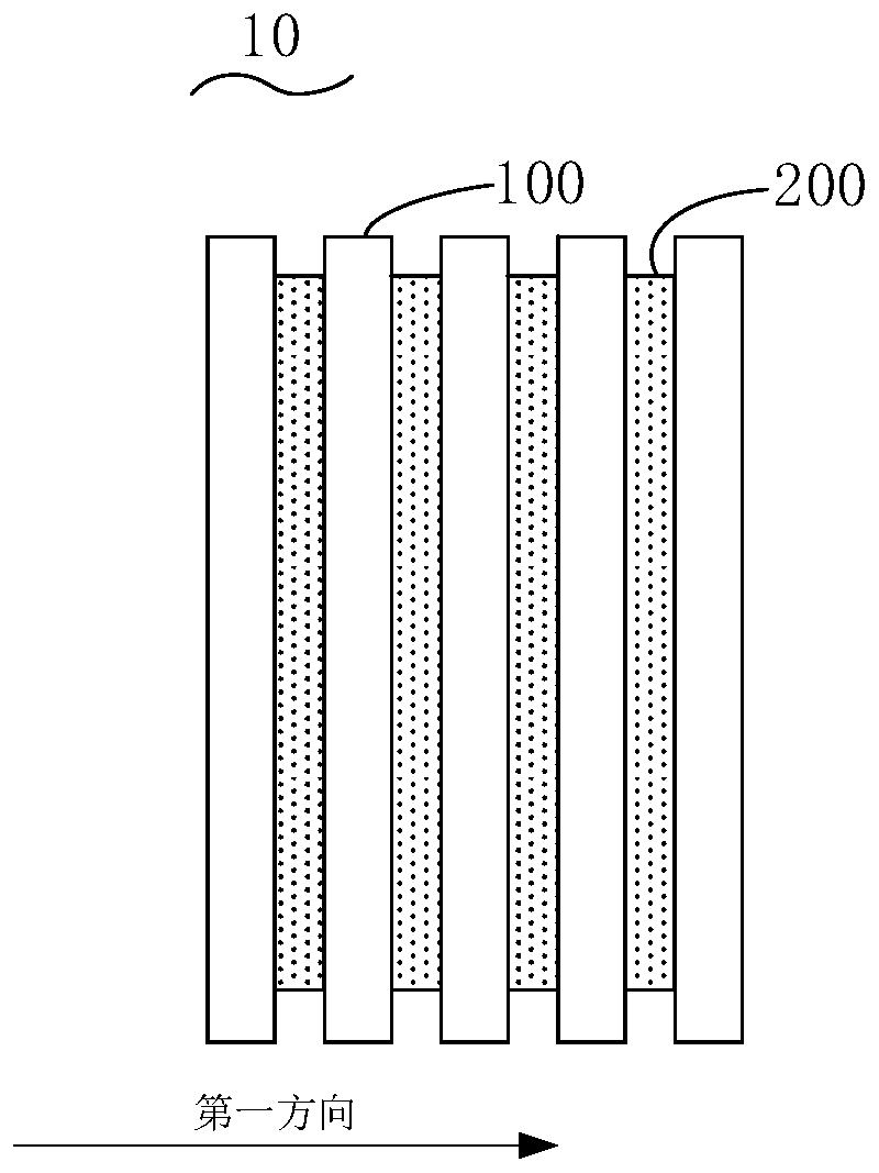
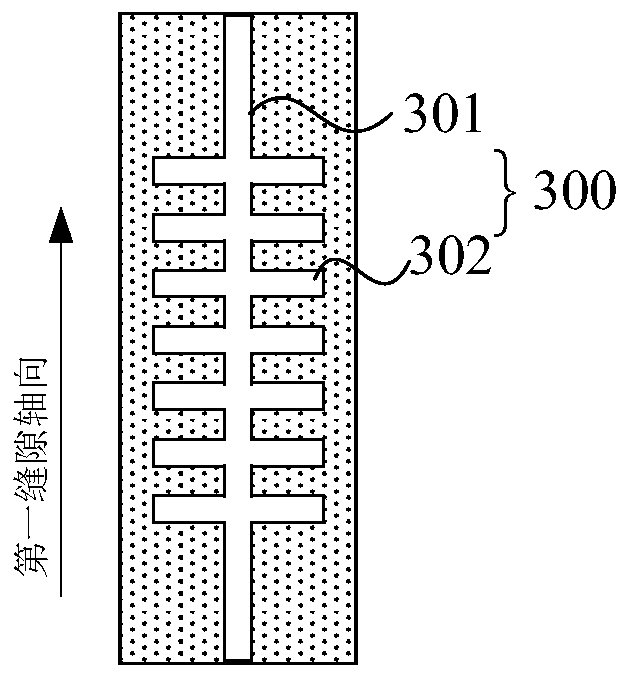
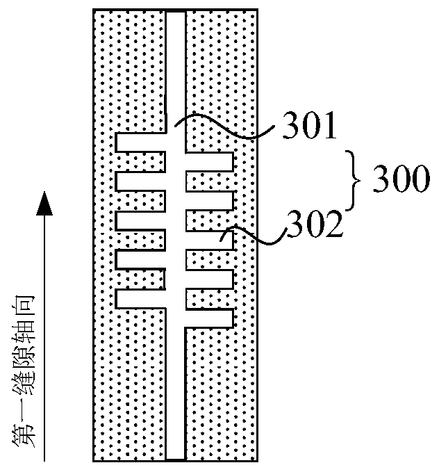
The invention relates to a lens structure, a lens antenna and electronic equipment. According to the lens structure, the artificial surface plasmon waveguide can be generated by utilizing a pluralityof pairs of second slots, by setting the gradual change rule of the number of the second slots of an inter-layer or intra-layer slot units, a phase delay distribution rule is obtained to realize a beam convergence function, and the dielectric loss of electromagnetic waves in the waveguide transmission process is low, so that the lens antenna with lower loss, higher efficiency and larger broadbandcan be realized in practical application. In addition, through the dielectric layers and the conductive layers which are alternately laminated, the assembly and preparation of the low-cost lens can berealized.

Description

technical field [0001] The present application relates to the technical field of antennas, in particular to a lens structure, a lens antenna and electronic equipment. Background technique [0002] The lens antenna is an antenna composed of a lens and a feed source. Using the converging characteristics of the lens, it can ensure that the electromagnetic waves emitted by the feed source pass through the lens in parallel, or that the parallel incident electromagnetic waves pass through the lens and converge to the feed source. Since the electromagnetic wave enters the lens, it generally needs to pass through multiple dielectric layers, and the introduction of the medium will cause the loss of the electromagnetic wave, thereby reducing the efficiency of the lens antenna. Contents of the invention [0003] Based on this, it is necessary to provide a lens structure, a lens antenna and an electronic device capable of improving the efficiency of the lens antenna. [0004] In orde...

Claims


Application Information

Patent Timeline
Patent Type & Authority Applications(China)
IPC IPC(8): H01Q15/02H01Q19/06H01Q21/00H01Q1/22
CPCH01Q1/22H01Q15/02H01Q19/06H01Q21/0006
Inventor 杨帆
Owner GUANGDONG OPPO MOBILE TELECOMM CORP LTD
Learn More