
Battery box with heat dissipation structure

A technology of heat dissipation structure and battery box, applied in the direction of secondary batteries, structural parts, battery pack parts, etc., can solve the problems of heat generation, not easy to dissipate heat, and affecting the time required for the battery to be fully charged.

Active Publication Date: 2020-02-07
ZHENGZHOU AFFIRMATIVE TECH LTD
View PDF7 Cites 9 Cited by
  • Summary
  • Abstract
  • Description
  • Claims
  • Application Information

AI Technical Summary

Problems solved by technology

In addition, the battery will also generate heat during charging, which will also affect the time required for the battery to be fully charged to a certain extent.
[0003] Due to the special working environment of the battery, it needs to be waterproof, dustproof, etc., so the structure design of the battery box is relatively closed, resulting in poor heat dissipation
[0004] In order to improve heat dissipation, such as a battery pack fast charging device disclosed in the invention patent application publication number CN107026489A, the charging device is provided with a heat dissipation fan and a heat dissipation port on the side of the battery pack, which can only dissipate heat to a certain extent, such as The battery cells of commonly used lithium battery components are stacked side by side, which is not easy to dissipate heat; in addition, more heat dissipation ports are opened, which may reduce the adaptability to the use environment

Method used


Image

  • Battery box with heat dissipation structure
  • Battery box with heat dissipation structure
  • Battery box with heat dissipation structure

Examples


Embodiment Construction

[0033] The following will clearly and completely describe the technical solutions in the embodiments of the present invention with reference to the drawings in the embodiments of the present invention.

[0034] An embodiment of a battery box with a heat dissipation structure of the present invention:

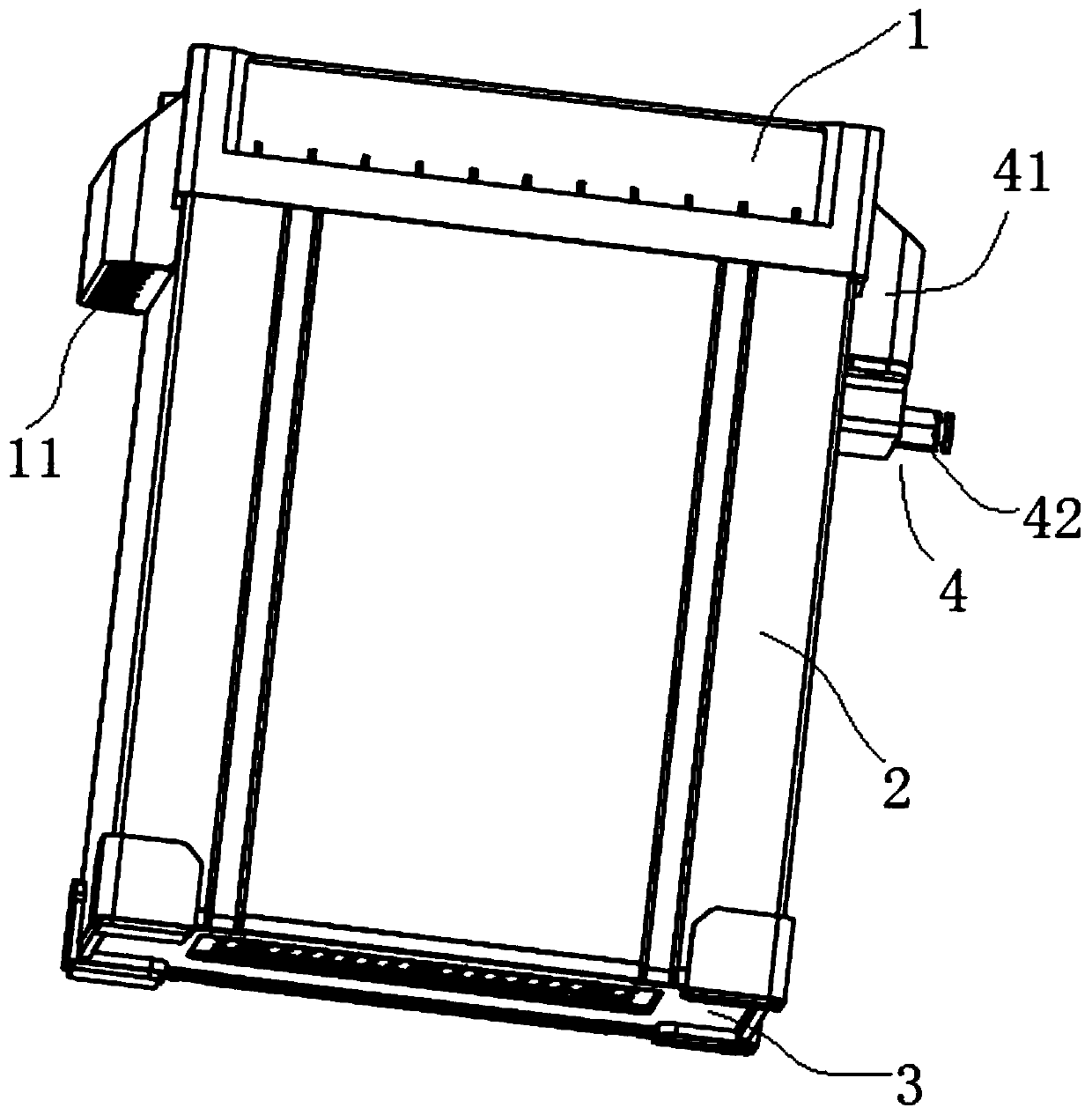
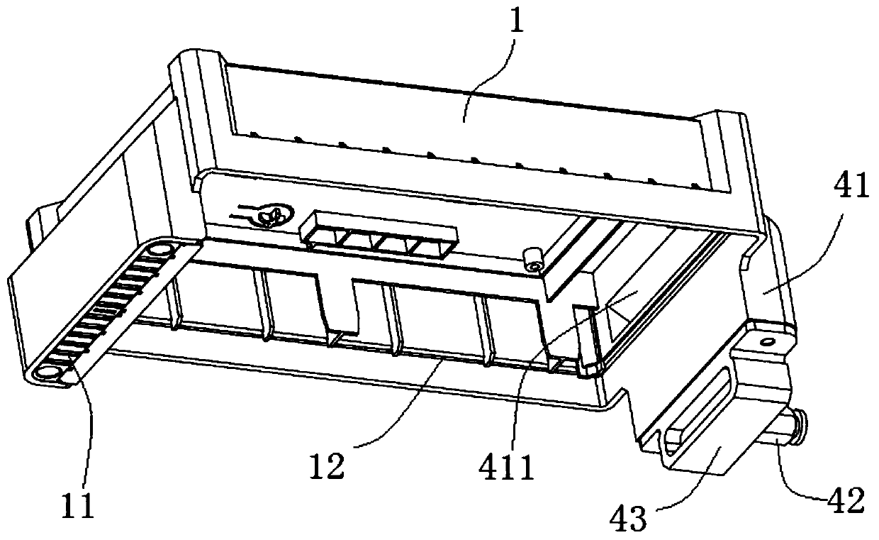
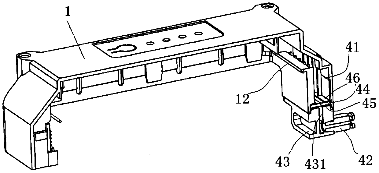
[0035] Such as Figure 1-Figure 10 As shown, the battery box with a heat dissipation structure includes an outer shell and a battery assembly. The outer shell includes an upper shell 1, a middle shell 2, and a lower shell 3. The three are fixed by screws. The upper shell 1 and the middle shell 2 The joints of the middle housing 2 and the lower housing 3 are provided with sealing rings, which are respectively recorded as the upper sealing ring 12 and the lower sealing ring 30. The left side of the upper housing 1 is provided with a charging socket 11, which is mated with a charging plug when charging. The right side of the upper casing 1 is provided with a one-way air inlet str...


PUM


Abstract

The invention relates to a battery box with a heat dissipation structure. The battery box comprises an outer housing and a battery assembly. A one-way air inlet structure is arranged on one side of the upper portion of the outer housing; and a one-way air outlet structure is arranged at the bottom of the outer housing. The battery assembly is arranged on a connecting board in the outer housing, and the battery assembly comprises a plurality of battery cores. A ventilation and heat dissipation board is arranged between every two adjacent battery cores; the upper ends of the battery cores are arranged on the connecting board, and the lower ends of the battery cores are supported on a ventilation board; and a plurality of ventilation holes are formed in the ventilation board. The one-way airinlet structure comprises an air inlet connector and an air inlet pad, wherein the air inlet pad only allows air to enter the outer housing from outside, and the air inlet connector is used for beingconnected with an air supply mechanism. The one-way air outlet structure comprises an air outlet pad, wherein the air outlet pad only allows air in the outer housing to flow out of the outer housing.The battery box can solve the heat dissipation problem in the high-temperature battery charging process, so that the battery charging speed can be remarkably increased, and the service life of the battery is prolonged.

Description

technical field [0001] The invention relates to the technical field of rechargeable batteries, in particular to a battery box with a heat dissipation structure. Background technique [0002] Plant protection UAV, also known as unmanned aerial vehicle, as the name implies, is an unmanned aircraft used for agricultural and forestry plant protection operations. Composed of three parts, the spraying operation can be realized through ground remote control or navigation flight control, which can spray chemicals, seeds, powder, etc. A kind of plant protection unmanned aerial vehicle disclosed as the utility model patent of authorized announcement number CN206367594U. Most plant protection drones use replaceable and rechargeable batteries as power sources. A battery has limited battery life. After the drone has been working for a period of time, it is necessary to replace a fully charged battery before continuing to work. The battery generates a lot of heat during the discharge pr...

Claims


Application Information

Patent Timeline
Patent Type & Authority Applications(China)
IPC IPC(8): H01M2/10H01M10/613H01M10/6554H01M10/6563
CPCH01M10/613H01M10/6554H01M10/6563H01M50/20Y02E60/10
Inventor 王科锋
Owner ZHENGZHOU AFFIRMATIVE TECH LTD
Learn More