
Lever-cutting shock wave energy passive measurement sensor

A passive measurement and shock wave technology, applied in the direction of blasting force measurement, can solve the problems of difficult wiring, electromagnetic interference, cumbersome processing procedures, etc., and achieve the effect of rapid quantitative passive measurement

Active Publication Date: 2020-02-07
NAT UNIV OF DEFENSE TECH
View PDF5 Cites 1 Cited by
  • Summary
  • Abstract
  • Description
  • Claims
  • Application Information

AI Technical Summary

Problems solved by technology

[0009] The technical problem to be solved by the present invention is to provide a lever-cut shock wave energy passive measurement sensor, which uses the principle of leverage to improve the sensitivity of the sensor, and solves the problem of wiring difficulties and electromagnetic interference in the electrical measurement active sensor used in the existing active measurement method. Difficult problem; make up for the shortcomings of existing passive measurement methods, such as cumbersome post-measurement processing procedures, complex measurement systems, or the need for auxiliary measurement by electrical measurement equipment

Method used


Image

  • Lever-cutting shock wave energy passive measurement sensor
  • Lever-cutting shock wave energy passive measurement sensor
  • Lever-cutting shock wave energy passive measurement sensor

Examples


Embodiment Construction

[0039] In order to facilitate those skilled in the art to understand and implement the patent of the present invention, the present invention will be further described in detail below in conjunction with the accompanying drawings and specific embodiments.

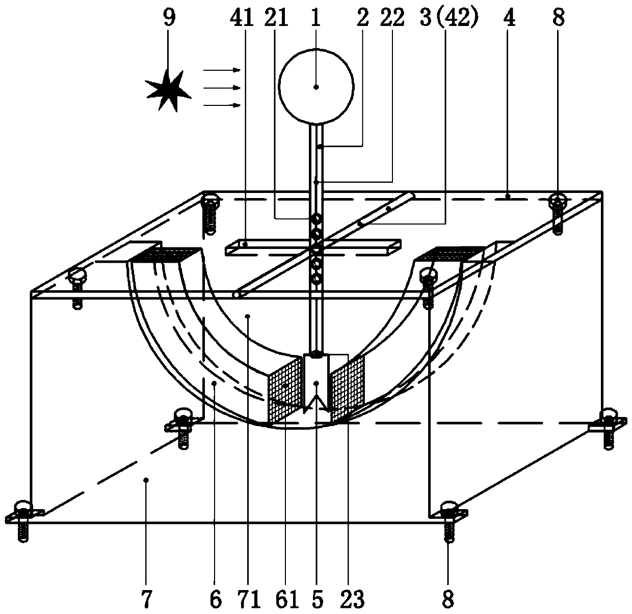
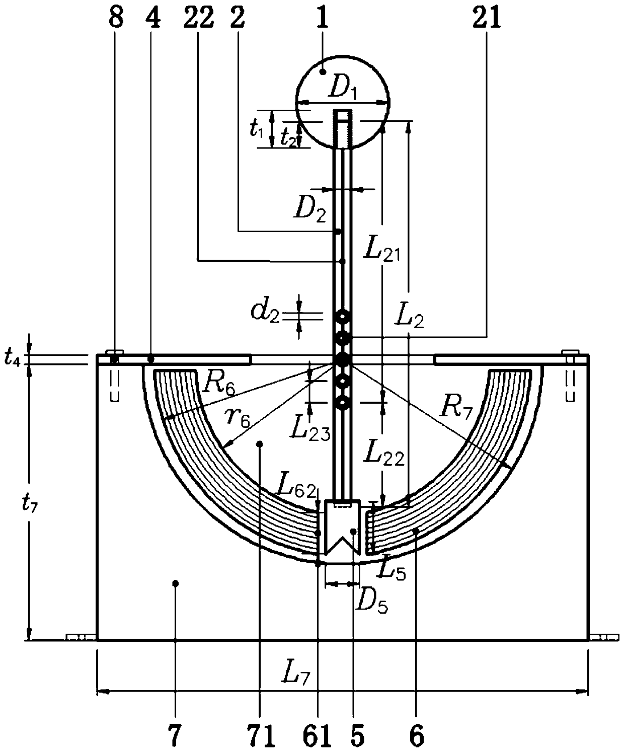
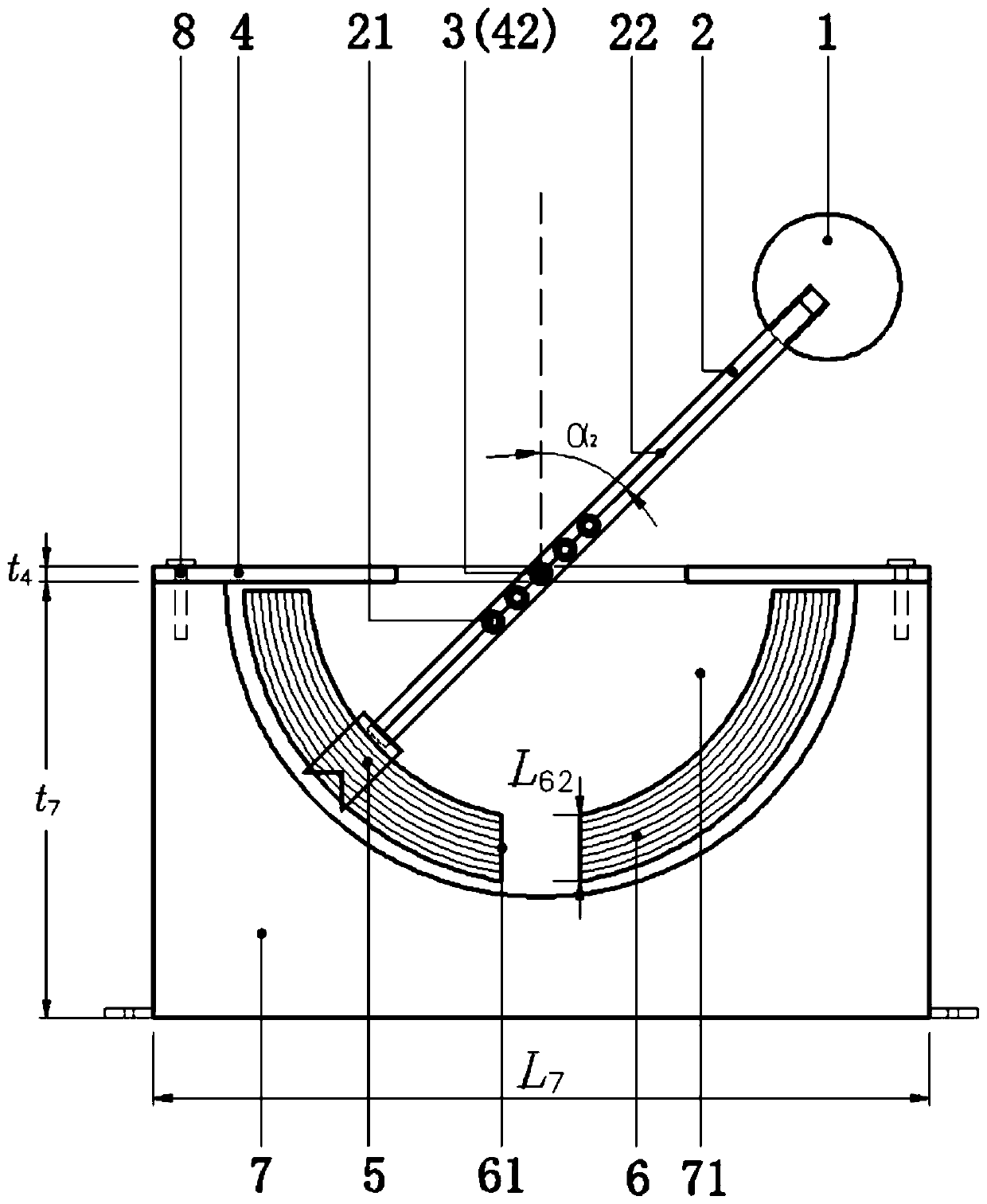
[0040] figure 1 It is a schematic diagram of the overall structure of the present invention. Such as figure 1As shown, the present invention is made up of windward ball 1, rocking bar 2, support rod 3, cover plate 4, blade 5, energy-absorbing member 6, base 7, movable bolt 8. The end that defines the present invention near explosion point 9 is the left end, and the end that defines the present invention away from explosion point 9 is the right end. The windward ball 1 is fixed on the top of the rocker 2 through the screw hole and the thread, the blade 5 is fixed on the bottom of the rocker 2 through the slot 23, the rocker 2 is connected with the support rod 3 through the rolling bearing 21, and the support rod 3 is inser...


PUM

PropertyMeasurementUnit
Lengthaaaaaaaaaa
Thicknessaaaaaaaaaa
Yield strengthaaaaaaaaaa

Abstract

The present invention discloses a lever-cutting shock wave energy passive measurement sensor. The sensor is composed of a windward ball, a rocking bar, a supporting bar, a cover plate, a blade, an energy-absorption component, a base and a movable bolt. Centers of the windward ball, the supporting bar, the cover plate, the blade and the base are all on an axis of the rocking bar. The windward ball,the rocking bar, the cover plate and the base generate no plastic deformation under effect of an explosive shock wave. Under effect of the shock wave, the windward ball moves, the rocking bar drivesthe blade to cut the energy-absorption component, and the energy-absorption component is broken. A rotation angle of the rocking bar is measured, a cutting embedding displacement of the blade is calculated, and passive quantitative measurement of shock wave energy is implemented by using a quantitative relation between a cutting embedding displacement amount and absorbed energy. The sensor has a simple structure, needs no power supply, is convenient for layout, low in costs and reusable, and has high response sensitivity for shock waves of different strengths, so that a technical problem thatquantitative test is hard to be performed on shock wave energy in a severe environment is resolved.

Description

technical field [0001] The invention belongs to the field of measurement and detection, and specifically relates to a sensor for measuring shock wave parameters generated by an explosion. Background technique [0002] When the explosive explodes in the air, high-temperature, high-pressure, and high-speed explosion products are produced instantly, and the surrounding air is directly affected by the explosion products. At the interface between the explosive and the air, the explosion products fly around at a very high speed in the air, as A supersonic piston violently compresses the adjacent air medium, causing its pressure, density, and temperature to increase step-by-step, forming an initial shock wave. Air shock wave is one of the main factors for the damage and damage effect of ammunition explosion on personnel, equipment and protective structures, so the analysis and test of shock wave are of great significance in both military and civilian fields. [0003] The methods o...

Claims


Application Information

Patent Timeline
IPC IPC(8): G01L5/14
CPCG01L5/14
Inventor 林玉亮祁子真张玉武陈荣李翔宇卢芳云梁民族李志斌彭永
Owner NAT UNIV OF DEFENSE TECH
Learn More