
Artificial limb knee joint control method

A control method and technology of knee joint, applied in the field of communication, can solve the problems of not considering typical motion state, difficult to achieve ideal effect, unable to provide, etc., to achieve the effect of reducing exercise burden, light weight and simple assembly

Active Publication Date: 2020-02-07
浙江臻行科技有限公司
View PDF14 Cites 1 Cited by
  • Summary
  • Abstract
  • Description
  • Claims
  • Application Information

AI Technical Summary

Problems solved by technology

However, the control method using the Hall sensor needs to collect the user's gait information first, then install the sensor, and then control it, which is inconvenient to use.
The damper it uses is a cylinder damper. Since the gas is relatively easy to compress, it cannot provide a high moment, and it is difficult to achieve the desired effect during the support phase.
Moreover, the control method provided is only a control method with different speeds on flat ground, and does not consider other typical motion states such as uphill and downhill, etc.

Method used


Image

  • Artificial limb knee joint control method
  • Artificial limb knee joint control method

Examples


Embodiment Construction

[0038] In order to make the object, technical solution and advantages of the present invention clearer, the present invention will be described in further detail below with reference to the accompanying drawings and preferred embodiments. However, it should be noted that many of the details listed in the specification are only for readers to have a thorough understanding of one or more aspects of the present invention, and these aspects of the present invention can be implemented even without these specific details.

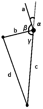
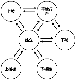
[0039] The prosthetic knee joint control method provided in this embodiment is that the processor establishes a simplified model of the prosthetic leg, collects the ground support reaction force data according to the pressure sensor installed on the prosthetic foot, and then according to the angle sensor installed on the prosthetic leg knee joint, Obtain the knee joint rotation angle data; according to the support reaction force data and the knee joint rotation an...


PUM


Abstract

The invention discloses an artificial limb knee joint control method, which is characterized in that a processor builds an artificial limb simplified model, the ground bearing reaction data is collected according to a pressure sensor installed on an artificial foot, and the knee joint corner data is obtained according to an angle sensor installed on an artificial leg knee joint; the data is compared in a gait database according to the bearing reaction data and the knee joint corner data, and the gait period identification and motion state identification are carried out by the processor; the processor is used for identifying and controlling the damping of a hydraulic cylinder according to the motion state and changing the action of the artificial limb. The defect that the moment of force isinsufficient when a pneumatic cylinder supports a phase is overcome, and a control method of an artificial limb user in different motion states is provided, so that the user can move more naturally.

Description

technical field [0001] The invention relates to the field of communication technology, in particular to a method for controlling a prosthetic knee joint. Background technique [0002] According to the data, due to factors such as diseases, traffic accidents, work-related injuries, and natural disasters, the number of thigh amputee patients has increased year by year, which has caused a great burden on the patient's family and society. The installation of artificial limbs can restore the mobility of thigh amputee patients. The prosthetics currently on the market are generally mechanical prostheses. By providing fixed damping, it is very inconvenient to use the mechanical structure to drive the prosthetics to move. With the development of electronic information technology, in order to make the movement of prosthesis users more convenient, smart prostheses that use control elements to dynamically adjust joint dynamics to adapt to the wearer's walking state have emerged. [000...

Claims


Application Information

Patent Timeline
IPC IPC(8): A61F2/70
CPCA61F2/68A61F2002/6827A61F2002/6872A61F2002/701
Inventor 张岩岭玄利圣李哲
Owner 浙江臻行科技有限公司
Learn More