
High-simulation robot head structure and motion control method thereof

A technology of simulating robots and robots, which is applied in the field of robots, can solve the problems of incapable of novel and interesting consumption experience, stiff facial expressions, lack of human interaction functions, etc., and achieve the effect of real and vivid service experience

Pending Publication Date: 2018-02-23
深圳市小村机器人智能科技有限公司
View PDF9 Cites 6 Cited by
  • Summary
  • Abstract
  • Description
  • Claims
  • Application Information

AI Technical Summary

Problems solved by technology

[0003] In view of this, the main purpose of the present invention is to provide a highly simulated robot head structure and its motion control method, aiming to solve the problem of using traditional steering gear to provide Kinetic energy, resulting in rigid facial expressions and lack of the function of interacting with real people, making it impossible to provide consumers with novel and interesting consumption experiences in the service industry

Method used


Image

  • High-simulation robot head structure and motion control method thereof
  • High-simulation robot head structure and motion control method thereof
  • High-simulation robot head structure and motion control method thereof

Examples


Embodiment 1

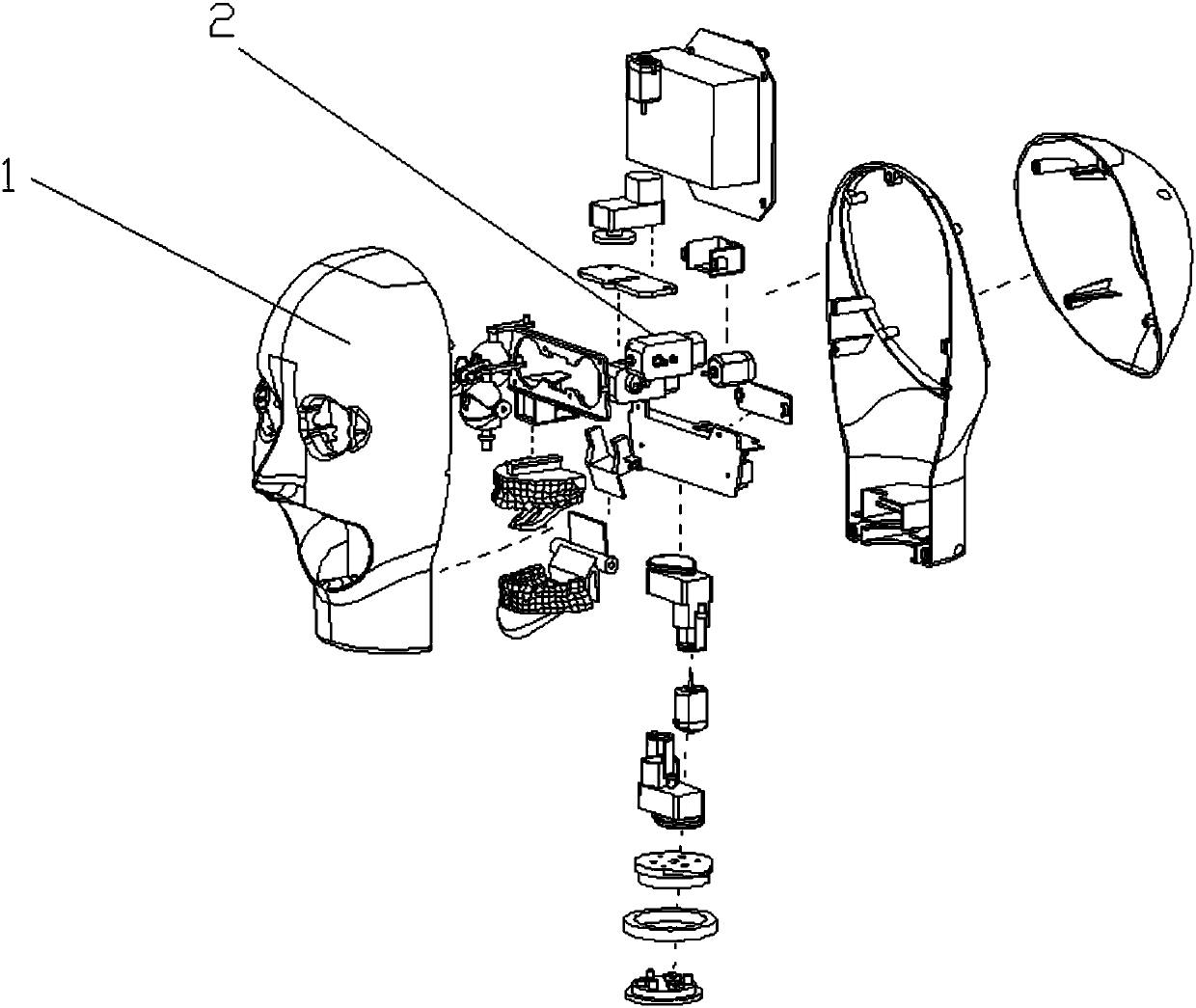
[0060] refer to Figure 1 to Figure 5 , the highly simulated robot head structure and operating system includes a shell component 1 , a facial movement component 2 and an internal control component 3 arranged inside the shell component 1 .

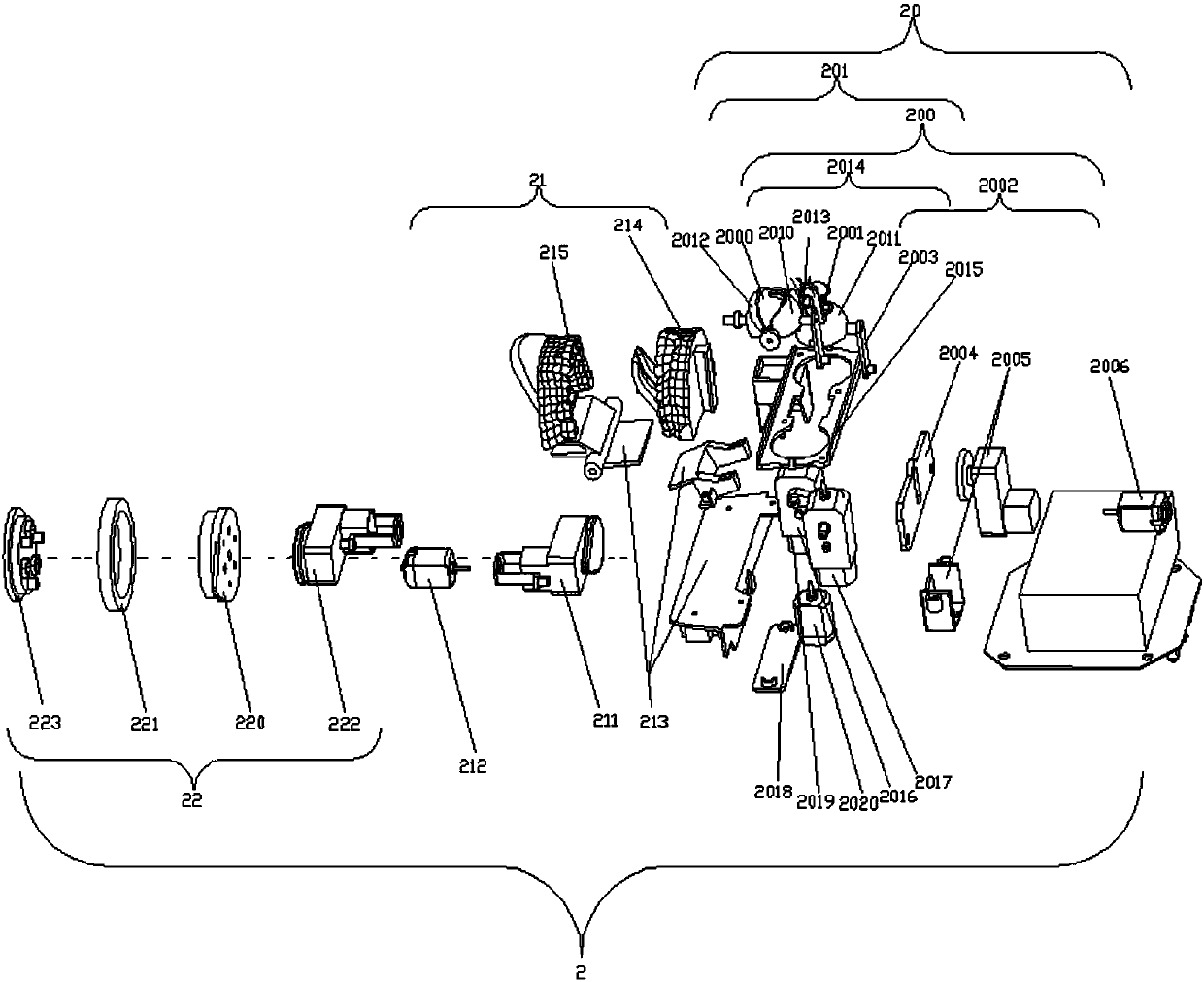
[0061] The facial movement assembly 2 includes an eye assembly 20 and a mouth assembly 21 , and the eye assembly 20 specifically includes an eyeball assembly 200 and an eyelid assembly 201 .

[0062] Wherein, the eyeball assembly 200 is connected with the internal control assembly 3 through the eyeball transmission assembly 2002 provided with the first motor 2006; connect.

[0063] The mouth assembly 21 is connected with the internal control assembly 3 through the fourth motor 212 inside the mouth assembly 21 .

[0064] Described internal control assembly 3 comprises main processor 30 and the active control assembly that is connected with main processor 30 respectively, external induction module 33, voice module 32, database module 35 an...

Embodiment 2

[0071] refer to image 3 , the eyelid assembly 201 includes an upper left eyelid 2010 and a lower left eyelid 2012 arranged on the left eyeball 2000 ; an upper right eyelid 2011 and a lower right eyelid 2013 arranged on the right eyeball 2001 .

[0072] The eyelid assembly 201 fully imitates the eyelid structure of a real person, and is provided with an upper left eyelid 2010, a lower left eyelid 2012, an upper right eyelid 2011, and a lower right eyelid 2013. Two motors control the eyelid assembly 201, that is, the second motor 2017 controls the upper left eyelid 2010 and the upper right eyelid 2011, and the third motor 2020 controls the lower left eyelid 2012 and the lower right eyelid 2013, so that the degree of simulation is significantly improved, and the facial expressions are more vivid. stiff.

[0073] refer to image 3 , the upper and lower eyelid transmission assembly 2014 also includes the upper eyelid gear box 2016 connected with the second motor 2017; the upper ...

Embodiment 3

[0076] refer to image 3 , the mouth assembly 21 also includes a mouth core wheel 211 connected with the fourth motor 212; a mouth gear 210 connected with the mouth core wheel 211; a mouth transmission member 213 connected with the mouth gear 210; The upper gear part 214 and the lower gear part 215 connected by the upper transmission part 213 .

[0077] The fourth motor 212 drives the mouth core wheel 211 to rotate, thereby driving the mouth gear 210, and the mouth gear 210 drives the mouth transmission part 213, so that the mouth transmission part 213 drives the upper gear part 214 and the lower gear part 215 to simulate The opening and closing of the human mouth.

[0078] refer to image 3 , the neck assembly 22 comprises a neck gear box 222; a neck rotating part 220 connected with the neck gear box 222; a neck butt joint 221 connected with the neck turning part 220; a neck pressing part connected with the neck joint 221 223.

[0079] A motor can be installed on the exte...


PUM


Abstract

The invention discloses a high-simulation robot head structure and a motion control method thereof. The high-simulation robot head structure comprises a shell assembly, a face motion assembly and an internal control assembly. The face motion assembly comprises an eye assembly, a mouth assembly and a neck assembly. An eyeball assembly is connected with the internal control assembly through a firstmotor. An eyelid assembly is connected with the internal control assembly through a second motor and a third motor. The mouth assembly is connected with the internal control assembly through a fourthmotor. An expression control and management module, independently researched and developed by our company, for realizing expression actions can be added to the internal control assembly. The expression control and management module works in cooperation with the face assembly under the external silica gel skin to realize the changes of expressions. With the high-simulation robot head structure andthe motion control method thereof, it is solved that in the prior art, when a robot for the service industry simulates the facial expressions of a real human being, the facial expressions are stiff because a traditional actuator is adopted for providing kinetic energy, the robot is in lack of the function of interacting with real human beings, and the robot cannot provide new and interesting consumption experience for consumers in the service industry.

Description

technical field [0001] The invention relates to the field of robots, in particular to a highly simulated robot head structure and an action control method thereof. Background technique [0002] A robot is a machine device that performs work automatically. It can accept human command, run pre-programmed programs, and act according to principles formulated with artificial intelligence technology. Its mission is to assist or replace human work in jobs such as manufacturing, construction, or hazardous jobs. Therefore, it can be said that a robot is an actual space operation tool with biological functions, which can replace human beings to complete some dangerous or difficult labors and tasks. At present, when the robots used in the service industry on the market imitate the facial expressions of real people, most of them use traditional servos to provide kinetic energy, resulting in stiff facial expressions. At the same time, they are limited by the internal structure and cont...

Claims


Application Information

Patent Timeline
Patent Type & Authority Applications(China)
IPC IPC(8): B25J11/00B25J17/00B25J9/12B25J9/16B25J13/00
CPCB25J9/12B25J9/1612B25J11/00B25J13/00B25J17/00
Inventor 黄山李有松张沛滨
Owner 深圳市小村机器人智能科技有限公司
Learn More