
Electronic parking mechanism

An electronic parking and parking technology, applied in mechanical equipment, components with teeth, transmission control and other directions, can solve the problems of high processing precision, insufficient parking, parking stuck, etc., to achieve accuracy Good, reasonable layout, accurate power transmission effect

Active Publication Date: 2020-02-04
江西鼎盛新材料科技有限公司
View PDF8 Cites 5 Cited by
  • Summary
  • Abstract
  • Description
  • Claims
  • Application Information

AI Technical Summary

Problems solved by technology

At present, for the electronic parking mechanism, most of them adopt the driving screw to be directly connected with the parking motor to realize the power transmission of the parking motor. Since the self-locking of motion is to be realized, the driving screw generally adopts a screw nut mechanism (such as publication number CN205101548U patent documents), but the lead screw nut mechanism requires high machining accuracy, and there is a risk of parking stuck or parking not in place when there are impurities inside the mechanism

Method used


Image

  • Electronic parking mechanism
  • Electronic parking mechanism
  • Electronic parking mechanism

Examples


Embodiment 1

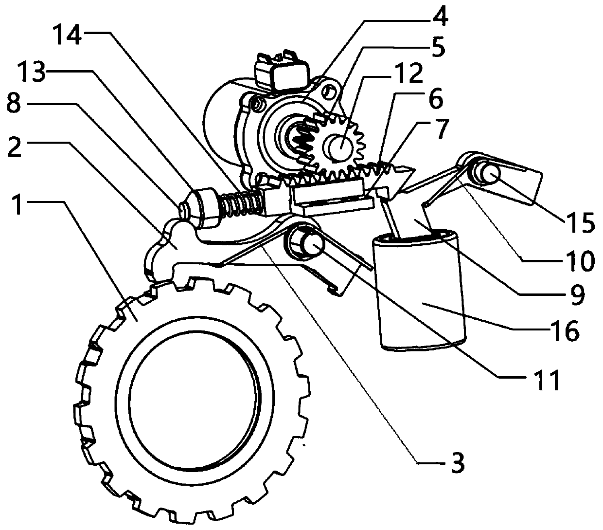
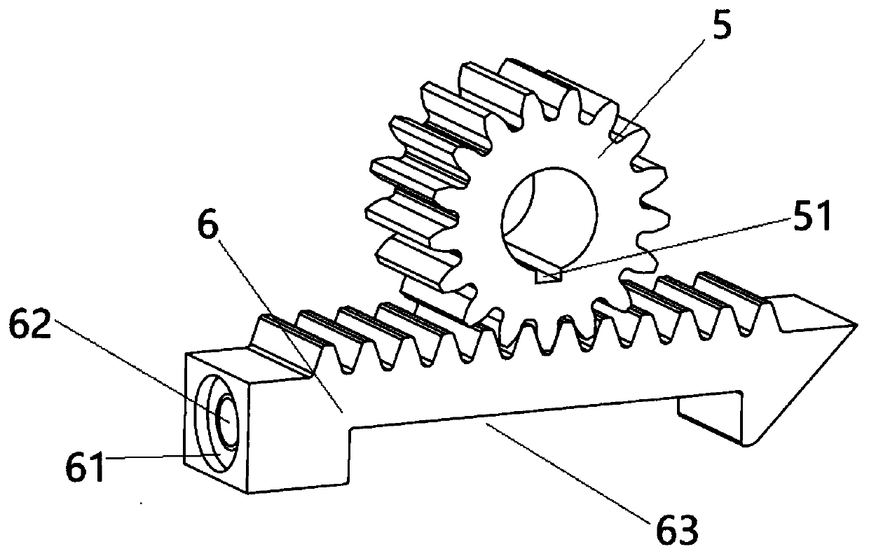
[0020] An electronic parking mechanism such as figure 1 As shown, it includes parking ratchet 1, parking pawl 2, pawl return spring 3, parking motor 4, gear 5, rack 6, rack guide rail 7, actuating lever 8, pawl 9 and pawl Return spring 10, one end of the parking pawl 2 is fixed on the gearbox casing (the gearbox casing is not shown in the figure) by the first fixed pin 11 and the parking pawl 2 can rotate around the first fixed pin 11 , the claw head at the other end of the parking pawl 2 is located above the parking ratchet wheel 1 and the claw head of the parking pawl 2 and the tooth groove of the parking ratchet 1 are matched and meshed with each other, and the center of the pawl return spring 3 is empty. On the first fixed pin 11, one end of the pawl return spring 3 is stuck on the parking pawl 2, the other end of the pawl return spring 3 is fixed on the gearbox case, and the parking motor 4 is installed on the gearbox case Outside the body and the motor shaft of the park...


PUM


Abstract

The invention provides an electronic parking mechanism. The electronic parking mechanism comprises a parking ratchet, a parking pallet, a pallet return spring, a parking motor, a gear, a rack, a rackguide rail and an actuating rod; the parking motor is mounted out of a transmission body; a motor shaft of the parking motor penetrates through the transmission body, and is connected with one end ofa gear shaft; the gear fixedly sleeves the gear shaft; the rack is positioned right under the gear; the gear is engaged with the rack; the rack is mounted on the rack guide rail, and can move in the axial direction of the rack guide rail; one end of the rack is fixed with one end of the actuating rod; an actuating block sleeves the other end of the actuating rod; an actuating spring is arranged onthe actuating rod; and an actuating surface of the actuating block is contacted with the inward side surface of the top of the parking pallet. The electronic parking mechanism is reasonable in layout, precise and smooth in power transfer, better in stability and precision and capable of preventing the parking blockage risk.

Description

technical field [0001] The invention relates to an electronic parking mechanism. Background technique [0002] The parking mechanism is an important part of the car, including hydraulic parking mechanisms, electronic parking mechanisms and mechanical parking mechanisms. At present, for the electronic parking mechanism, most of them adopt the driving screw to be directly connected with the parking motor to realize the power transmission of the parking motor. Since the self-locking of motion is to be realized, the driving screw generally adopts a screw nut mechanism (such as publication number CN205101548U patent document), but the lead screw nut mechanism requires high machining accuracy, and the risk of parking jams or insufficient parking is likely to occur when there are impurities inside the mechanism. Contents of the invention [0003] The present invention aims to provide an electronic parking mechanism with reasonable layout, precise and smooth power transmission, g...

Claims


Application Information

Patent Timeline
IPC IPC(8): F16H63/34
CPCF16H63/3425F16H63/3466
Inventor 朱涛钟发平谭高于海生章金乐况柏文何潇王加友庞雷保孙哲浩
Owner 江西鼎盛新材料科技有限公司
Learn More