Fuel flow estimation method for oil-way of air scoop

A technology of fuel flow and oil circuit, which is used in gas turbine installations, turbine/propulsion fuel delivery systems, fuel control of turbine/propulsion units, etc.

Active Publication Date: 2020-02-04
BEIJING POWER MACHINERY INST
View PDF3 Cites 0 Cited by
  • Summary
  • Abstract
  • Description
  • Claims
  • Application Information

AI Technical Summary

Problems solved by technology

[0004] The purpose of the present invention is to provide a method for calculating the pressure difference by using the collected oil pressure before and after the servo valve, and then using the pressure difference and the drive current of the servo valve to realize the method of estimating the fuel flow in the air funnel oil circuit, so as to solve the problem before and after the servo valve. The impact of large-scale changes in oil pressure on system control improves the accuracy of fuel flow estimation

Method used


Image

  • Fuel flow estimation method for oil-way of air scoop
  • Fuel flow estimation method for oil-way of air scoop
  • Fuel flow estimation method for oil-way of air scoop

Examples


Embodiment Construction

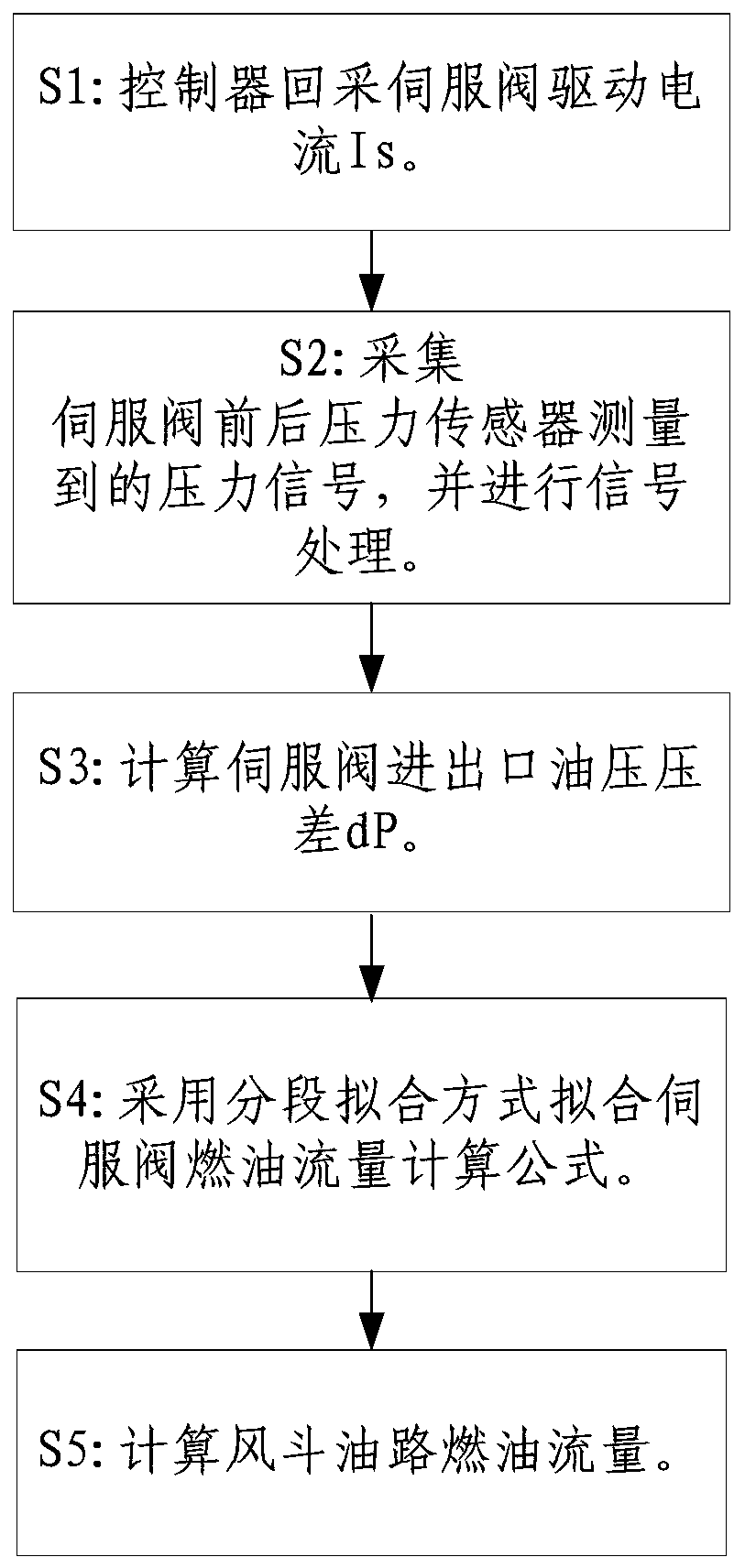
[0037] In order to make the purpose, content and advantages of the present invention clearer, the specific implementation manners of the present invention will be further described in detail below in conjunction with the accompanying drawings and embodiments.

[0038] refer to figure 1 As shown, the present invention firstly provides a fuel flow estimating system for the air bucket oil circuit, which includes a controller 1, a servo valve 2, a pre-valve oil pressure sensor 3, a post-valve oil pressure sensor 4, and a fuel flow calculation module 5; The inlet and outlet of the valve 2 are respectively equipped with the oil pressure sensor 3 before the valve and the oil pressure sensor 4 after the valve; the fuel flow calculation module 5 combines the driving current of the servo valve 2 and the pressure signals of the pressure sensors before and after the servo valve 2 to determine the fuel flow rate of the air bucket oil circuit. The estimation is performed, and the estimation...


PUM


Abstract

The invention discloses a fuel flow estimation system for an oil-way of an air scoop. The system comprises a controller (1), a servo valve (2), a fore-valve oil pressure sensor (3), a post-valve oil pressure sensor (4) and a fuel flow resolving module (5). The fore-valve oil pressure sensor (3) and the post-valve oil pressure sensor (4) are separately arranged at an inlet and an outlet of the servo valve (2); the fuel flow resolving module (5) is combined with a driving current of the servo valve (2) and pressure signals of pressure sensors in front of and behind the servo valve (2) to estimate the fuel flow of the oil-way of the air scoop, an estimation result is transferred to the controller (1), and the controller (1) adjusts the driving current of the servo valve (2) in real time. Theestimation system estimates the fuel flow of the oil-way of the air scoop by means of the collected oil pressure difference between the inlet and outlet of the servo valve and the driving current of the servo valve and improves the estimation precision of the fuel flow of the oil-way of the air scoop, so that influence of a large oil pressure range change in front of the servo valve to the systemis solved, and the system is wide in application range and high in calculating precision.

Description

technical field [0001] The invention belongs to the technical field of liquid ramjet engines, and relates to a method for estimating fuel flow in a wind bucket oil circuit. Background technique [0002] The hydraulic ramjet engine wind bucket oil circuit uses a servo valve to adjust the fuel flow. The traditional flow estimation method is to test and calibrate the opening of the servo valve, and estimate the corresponding fuel flow through the opening of the servo valve. Although this method is simple to implement and easy to implement in engineering, the estimation accuracy is low, and it cannot adapt to the influence of large-scale changes in fuel pressure before the servo valve on the system. Contents of the invention [0003] (1) Purpose of the invention [0004] The purpose of the present invention is to provide a method for calculating the pressure difference by using the collected oil pressure before and after the servo valve, and then using the pressure difference...

Claims


Application Information

Patent Timeline
Patent Type & Authority Applications(China)
IPC IPC(8): F02C9/32F02C9/28
CPCF02C9/263F02C9/28F02C9/32
Inventor 张业敏裘云杨锡武卢彬景艳艳
Owner BEIJING POWER MACHINERY INST
Why Eureka
Try Eureka