
Bottom mould linking device for bottle blowing machine

The technology of a linkage device and a blow molding machine is applied in the field of rotary blow molding machines, which can solve the problems of the influence of the replacement of the rotary blow molding machine, the difficulty of springs to overcome the moment of inertia, and the sensitivity of limiting the opening and closing of the mold base, and achieve the structure Simple, well-setup, noise-reducing effect

Pending Publication Date: 2020-02-04
JIANGSU CHINA BEVERAGE MACHINERY
View PDF0 Cites 2 Cited by
  • Summary
  • Abstract
  • Description
  • Claims
  • Application Information

AI Technical Summary

Problems solved by technology

Although the mechanical drive structure has many advantages, it also limits the sensitivity of the mold base opening and closing
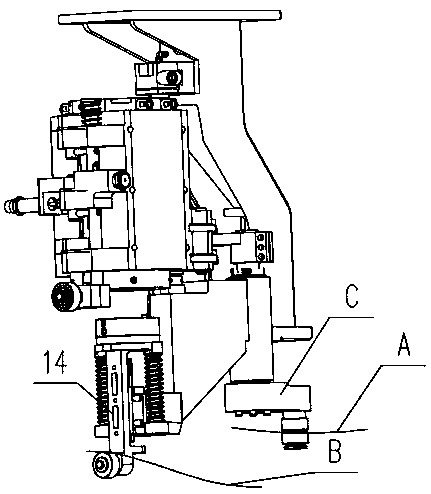
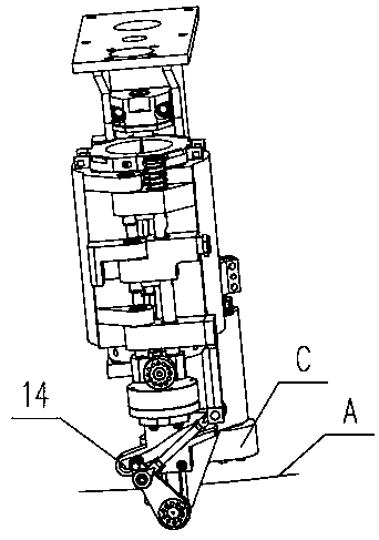
When the single-mode speed increases to a certain value, it is difficult for the spring on the bottom mold support to overcome the moment of inertia of the mold base, resulting in the bottom mold support being under the action of the moment of inertia, and the bottom mold support bearing cannot fit the curved movement of the bottom mold guide rail. , resulting in a jumping impact between the bottom mold support bearing and the bottom mold guide rail
[0004] The above phenomenon seriously restricts the increase of equipment output, and has an immeasurable impact on the replacement of rotary blow molding machines.

Method used


Image

  • Bottom mould linking device for bottle blowing machine
  • Bottom mould linking device for bottle blowing machine
  • Bottom mould linking device for bottle blowing machine

Examples


Embodiment Construction

[0017] In order to more clearly illustrate the technical solutions in the embodiments of the present invention or the prior art, the following will briefly introduce the drawings that need to be used in the description of the embodiments or the prior art. Obviously, the accompanying drawings in the following description are only These are some embodiments of the present invention. For those skilled in the art, other drawings can also be obtained according to these drawings without any creative effort.

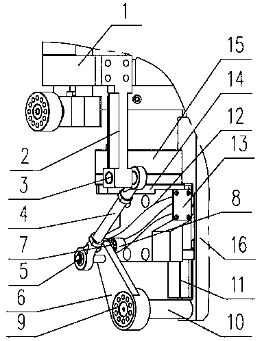
[0018] see as figure 1 , image 3 with Figure 4 As shown, this specific embodiment adopts the following technical scheme: it includes a fixed mold base 1, a fixed rod 2, a first joint bearing connecting shaft 3, an adjustable connecting rod 4, a second joint bearing connecting shaft 5, and a bottom mold swing arm 6. The first bearing connecting shaft 7, the first bearing 8, the second bearing 9, the fixed shaft 10, the guide rail slider 11, the small guide rail 12, the seal...


PUM


Abstract

The invention discloses a bottom mould linking device for a bottle blowing machine, and relates to the technical field of rotary type bottle blowing machines. The upper end of a fixed rod is fixedly arranged on a mould frame of a fixed mould, the lower end of the fixed rod is equipped with a joint bearing connecting shaft, the upper end of a bottom mould swing arm is separately equipped with a second joint bearing connecting shaft and a first bearing connecting shaft, one end of the first bearing connecting shaft is fixed with a first bearing, the two ends of an adjustable connecting rod are separately fixed with joint bearings, the joint bearings at the two ends are separately connected to the first joint bearing connecting shaft and the second joint bearing connecting shaft, the lower end of the bottom mould swing arm is connected to a fixed shaft through a second bearing, one end of a guide rail slide block is fixedly arranged on a mould frame bracket, the other end of the guide rail slide block is connected to a bottom mould bracket, and a curve slot is formed in a small guide rail. Under a high-speed operation condition of the bottom mould bracket, the bottom mould bracket slides up and down smoothly through guide motion, along a small guide rail curve slot, of the first bearing, so that mould frame opening and closing flexibility is improved, and generated noises are remarkably reduced.

Description

technical field [0001] The invention relates to the technical field of a rotary bottle blowing machine, in particular to a bottom mold linkage device for a bottle blowing machine. Background technique [0002] The mold of the rotary blow molding machine is generally composed of three parts: the movable mold, the fixed mold and the bottom mold, and they are respectively installed on the movable mold frame, the fixed mold frame and the bottom mold bracket. The fixed mold base and the movable mold base are equipped with a mold locking mechanism for locking the movable and fixed mold bases in the mold clamping state. The mold base, bottom mold bracket and mold locking mechanism cooperate with each other to complete the 'opening' and 'closing' movements of the mold base. [0003] see as figure 2 As shown, the opening and closing methods of mold bases in the industry are mainly mechanical, that is, the movable mold base and the fixed mold base are driven by the opening and closi...

Claims


Application Information

Patent Timeline
Patent Type & Authority Applications(China)
IPC IPC(8): B29C49/56
CPCB29C49/56
Inventor 张俊张伟袁爱军秦天豪
Owner JIANGSU CHINA BEVERAGE MACHINERY
Learn More