Transparent LED display device and naked eye 3D display device

A display device and LED lamp bead technology, which is applied in the direction of identification devices, instruments, electrical components, etc., can solve the problems of limited movement mode, inability to realize high-resolution transparent display, etc., and achieve the best display effect

Pending Publication Date: 2020-01-31
SHENZHEN PHOTONIC CRYSTAL TECH CO LTD
View PDF1 Cites 0 Cited by
  • Summary
  • Abstract
  • Description
  • Claims
  • Application Information

AI Technical Summary

Problems solved by technology

Because this method uses a control rod through the center point to control the movement mechanism, the movement mode is also limited, and high-resolution transparent display cannot be realized.
[0004] Patent CN200510033694.X also announced a display mode in which a motor drives rollers or gears, then drives a transmission belt or chain, and then drives the movement of display components. Viewers on both sides can see images, but because the LED line array is single-sided, two The image seen by the side viewer is reversed

Method used


Image

  • Transparent LED display device and naked eye 3D display device
  • Transparent LED display device and naked eye 3D display device
  • Transparent LED display device and naked eye 3D display device

Examples


Embodiment 1

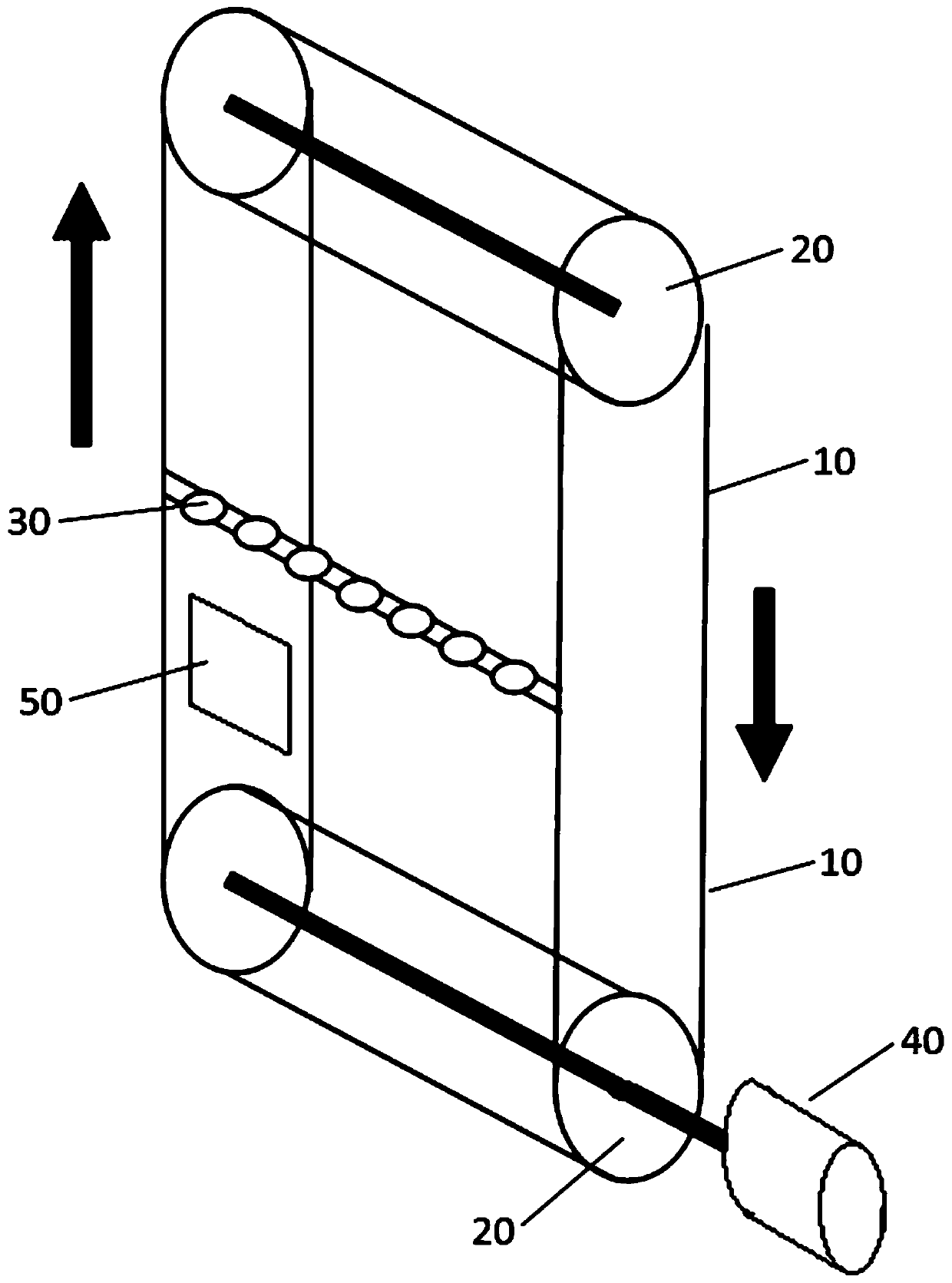
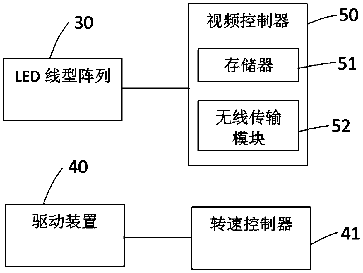
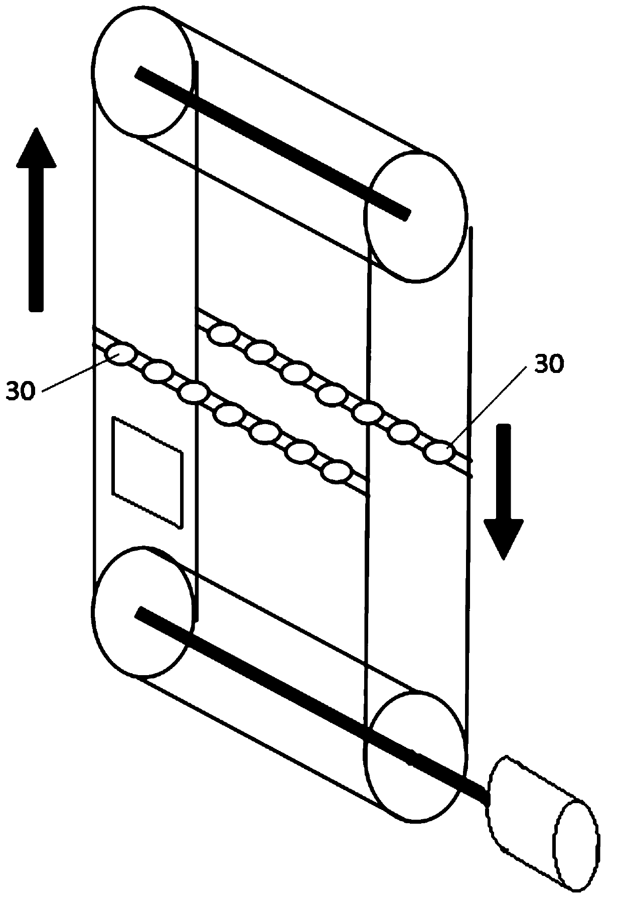
[0026] see figure 1 , figure 2 and image 3 , the present invention provides a transparent LED display device 80, comprising: an annular transparent strip 10, several rollers 20 in contact with the annular transparent strip 10, several LED wires arranged on the annular transparent strip 10 type array 30, a driving device 40, a speed controller 41 electrically connected to the driving device 40, a video controller 50 electrically connected to the LED linear array 30; the driving device 40 and a roller 20 connected, the annular transparent strip 10 is stretched by rollers 20 , and the LED linear array 30 includes at least one row of LED light bead linear array 31 . The driving device 40 drives the roller 20 to rotate, drives the annular transparent strip 10 to move, and the LED linear arrays 30 arranged on the annular transparent strip 10 also move, and the LED linear array 30 is controlled by the video controller 50 The different light intensity and color of each LED lamp b...

Embodiment 2

[0032] see Figure 5 , in this embodiment, the transparent LED display device 80 further includes: a brush 11 in contact with the annular transparent strip 10 . The brush 11 is connected to an external power source 12 , and the external power source 12 supplies power to the LED linear array 30 through the brush 11 .

Embodiment 3

[0034] see Figure 6 , in this embodiment, the LED linear array 30 includes: at least two LED lamp bead linear arrays 31 in the same direction, and the LED lamp beads in the LED lamp bead linear array 31 contain microlenses 32, and one of the LED lamp bead The bead line array 31 produces the image for the left eye, and the other LED light bead line array 31 produces the image for the right eye.


PUM


Abstract

The invention discloses a transparent LED display device. The LED display screen comprises an annular transparent strip, a plurality of rollers in contact with the annular transparent strip, a plurality of LED linear arrays arranged on the annular transparent strip, a driving device, a rotating speed controller electrically connected with the driving device, and a video controller electrically connected with the LED linear arrays. The driving device is connected with a roller, the annular transparent strip is tensioned by the roller, and the LED linear array at least comprises a row of LED lamp bead linear arrays. According to the invention, the LED linear array is arranged on the annular transparent strip, and the LED linear array can display dynamic content through the rotation of the annular transparent strip, so that transparent display is realized, and a better display effect is provided for a user. The invention further provides a naked eye 3D display device.

Description

technical field [0001] The invention relates to an LED display device, in particular to a transparent LED display device and a naked-eye 3D display device. Background technique [0002] Transparent LED display devices have attracted more and more attention in recent years. There are two main implementation methods: the first is to use transparent LED display screens. In fact, the principle of this transparent LED screen is the same as that of ordinary LED screens. , but some improvements have been made to the SMD manufacturing process of the LED light bar, the lamp bead packaging, and the control system. In addition, the hollow design is adopted to reduce the obstruction of the structural components to the line of sight and improve the permeability. There is an irreconcilable contradiction between the clarity and permeability of this transparent device, and it is generally only suitable for some large-scale display devices viewed from a distance. [0003] The second is to u...

Claims


Application Information

Patent Timeline
IPC IPC(8): H04N13/302G09F9/33
CPCG09F9/33H04N13/302
Inventor 王勇竞
Owner SHENZHEN PHOTONIC CRYSTAL TECH CO LTD
Why Eureka
Try Eureka