Eureka AIR delivers breakthrough ideas for toughest innovation challenges, trusted by R&D personnel around the world.

Liquid crystal display device and driving method thereof

A technology of a liquid crystal display device and a liquid crystal layer, which is applied in the direction of instruments, nonlinear optics, optics, etc., can solve the problems of inability to switch wide viewing angle mode, loss of brightness, and inability to realize partitioned display, etc., and achieve good display effect

Active Publication Date: 2020-06-23
KUSN INFOVISION OPTOELECTRONICS
View PDF4 Cites 6 Cited by
  • Summary
  • Abstract
  • Description
  • Claims
  • Application Information

AI Technical Summary

Problems solved by technology

[0004] In order to protect commercial secrets and personal privacy, shutter technology can be used, but this technology cannot be switched to wide viewing angle mode, and the brightness loss is serious. At the same time, the manufacturing cost is high, and it is difficult to meet the use requirements.
Moreover, the current switching between wide and narrow viewing angles generally only allows the display modes of all areas of the entire liquid crystal display device to be the same, and cannot achieve partitioned display.

Method used


Image

  • Liquid crystal display device and driving method thereof
  • Liquid crystal display device and driving method thereof
  • Liquid crystal display device and driving method thereof

Examples


no. 1 example

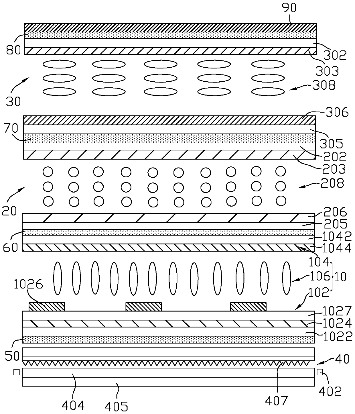
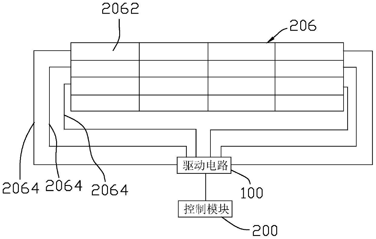
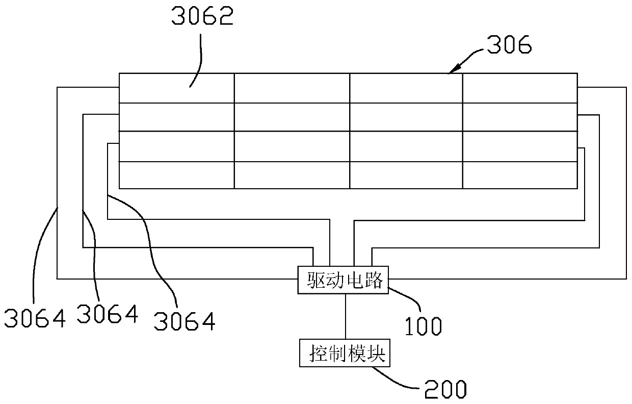
[0031] Please refer to figure 1 , the liquid crystal display device of the first embodiment of the present invention comprises a display panel 10, a first dimmer 20 and a second dimmer 30, and the first dimmer 20 and the second dimmer 30 are arranged on the same side of the display panel 10. Specifically, the first dimmer 20 is located between the display panel 10 and the second dimmer 30 . The first dimmer 20 is used to receive light in the up and down directions, and the second dimmer 30 is used to receive light in the left and right directions. The first dimmer 20 includes a first substrate 202 , a first electrode 203 , a second substrate 205 , a second electrode 206 and a first liquid crystal layer 208 . The first electrode 203 is arranged on the first substrate 202, the second electrode 206 is arranged on the second substrate 205, the first liquid crystal layer 208 is interposed between the first electrode 203 and the second electrode 206, and the first electrode 203 It...

no. 2 example

[0052] Such as Figure 7 As shown, the structure of the second embodiment of the present invention is similar to that of the liquid crystal display device of the above-mentioned first embodiment, the difference is that in the second embodiment, the first dimmer 20 and the second dimmer 30 are respectively Located on both sides of the display panel 10.

no. 3 example

[0054] Such as Figure 8As shown, the structure of the third embodiment of the present invention is similar to that of the liquid crystal display device of the above-mentioned first embodiment, the difference is that in the third embodiment, the liquid crystal display device only includes the first dimmer 20, at this time , the liquid crystal display device can only realize the upper and lower narrow viewing angle display mode and the wide viewing angle display mode. It can be understood that, in another embodiment, the liquid crystal display device may only include the second dimmer 30 , and in this case, the liquid crystal display device can only realize the left and right narrow viewing angle display modes and wide viewing angle display modes.


PUM


Abstract

The invention discloses a liquid crystal display device and a driving method thereof. The liquid crystal display device comprises a display panel and a first light modulator. The first light modulatoris arranged on one side of the display panel. The first light modulator is used for receiving light and comprises a first electrode, a second electrode and a first liquid crystal layer. The first liquid crystal layer is clamped between the first electrode and the second electrode, the first electrode is closer to a light emitting side of the liquid crystal display device than the second electrode, and the second electrode is divided into at least two sub-electrodes. According to the liquid crystal display device and the driving method thereof provided by the invention, wide-viewing-angle andnarrow-viewing-angle display can be realized by arranging the first light modulator, a penetration rate and a contrast ratio of front view are not influenced in a narrow-viewing-angle mode, and a display effect is good; moreover, the second electrode is divided into the plurality of sub-electrodes so that different voltages can be applied to the sub-electrodes, areas corresponding to the differentsub-electrodes are displayed in different display modes, and wide and narrow viewing angle partition display of the liquid crystal display device is realized.

Description

technical field [0001] The invention relates to the field of liquid crystal display technology, in particular to a liquid crystal display device and a driving method thereof. Background technique [0002] Liquid crystal display devices have the advantages of good image quality, small size, light weight, low driving voltage, low power consumption, no radiation, and relatively low manufacturing costs, and occupy a dominant position in the field of flat panel displays. [0003] With the continuous advancement of liquid crystal display technology, the viewing angle of the display has been expanded from about 120° to more than 160°. While enjoying the visual experience brought by the large viewing angle, people also hope to effectively protect commercial secrets and personal privacy. In order to avoid commercial loss or embarrassment caused by leakage of screen information. Therefore, in addition to the wide viewing angle, the display device is also required to have the function...

Claims


Application Information

Patent Timeline
IPC IPC(8): G02F1/13G02F1/1343G02F1/1347
CPCG02F1/1323G02F1/134309G02F1/1347
Inventor 邱郁雯穆兰
Owner KUSN INFOVISION OPTOELECTRONICS
Why Eureka
Eureka Blog
Learn More