Magnetorheological fluid flow mode rheological property testing device
A magnetorheological fluid and flow mode technology, applied in flow characteristics, measuring devices, instruments, etc., can solve problems such as inaccurate results, inaccurate test results, and inability to measure high shear rates of magnetorheological fluids, and achieve liquid The effect of high volume utilization, solving sealing difficulties and simple structure
- Summary
- Abstract
- Description
- Claims
- Application Information
AI Technical Summary
Problems solved by technology
Method used
Image
Examples
Embodiment 1
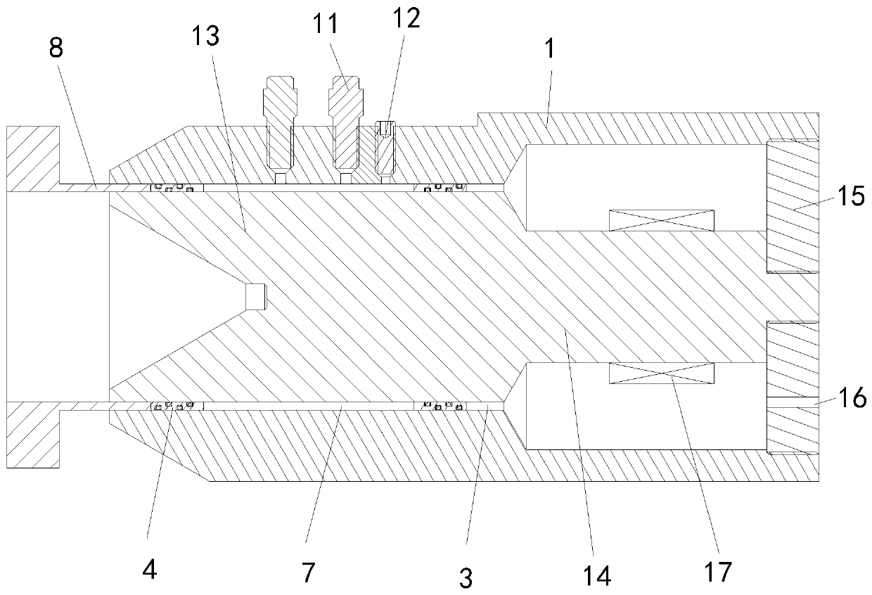
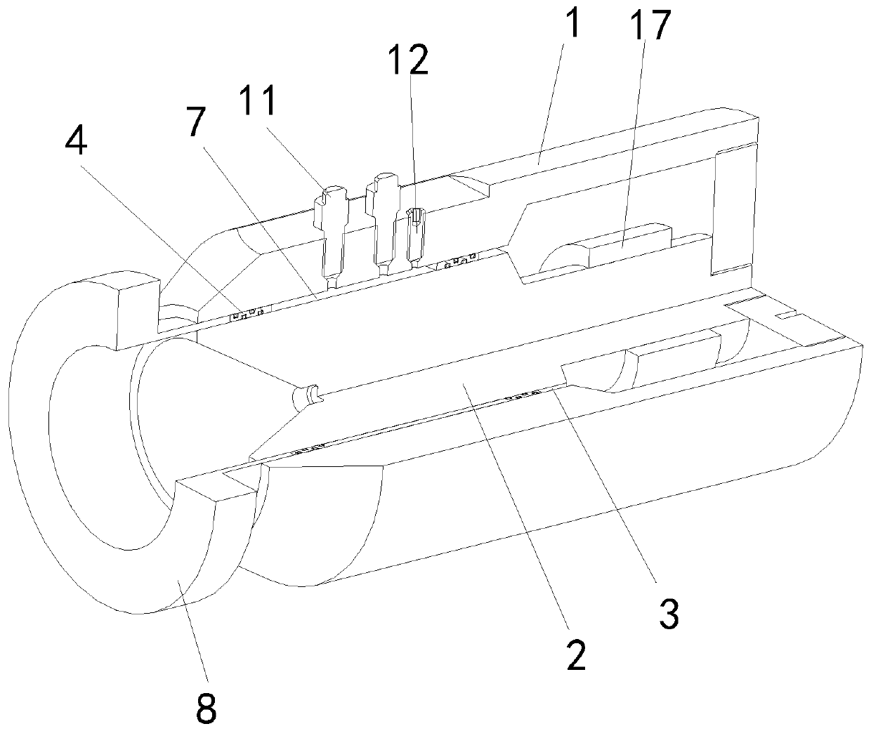
[0034] see Figure 1 to Figure 6 , this embodiment discloses a magnetorheological fluid flow mode rheological property testing device, including a shell 1 and an inner core 2 placed in the inner cavity of the shell 1, an annular gap 3 is provided between the shell 1 and the inner core 2, and the annular gap 3 There is an annular piston 4 inside, and the two ends of the annular piston 4 are respectively sealed and docked with the inner and outer walls of the annular gap 3, and the inner and outer walls of the two ends of the annular piston 4 are respectively provided with sealing rings 5, through which the sealing ring 5 and the annular gap 3 Inner wall or outer wall seal butt joint. The middle section of the annular piston 4 is provided with a slot 6, and the slot 6 and the inner and outer walls of the annular gap 3 together form a housing chamber 7 for accommodating the magnetorheological fluid. Under the action of the driving mechanism, the annular piston 4 can move in the a...
Embodiment 2
[0059] In the second embodiment, except that the installation structure of the coil winding is different from that of the first embodiment, other structural parts and testing procedures are the same as those of the first embodiment. In order to distinguish it from the structural name in Embodiment 1, the shell in this embodiment is represented by shell-18, the inner core is represented by inner core-24, the coil winding is represented by coil winding-20, and the annular gap is represented by annular To express the gap.
[0060] see Figure 7 to Figure 11 , In this embodiment, the installation structure of the coil winding 1 20 is: the coil winding 1 20 is installed on the housing 1 18 . The inner side of the housing one 18 is provided with two inwardly protruding ribs 19, the ribs 19 extend along the axial direction of the housing one 18, the two ribs 19 are oppositely arranged, and each rib 19 is wound with a coil winding 120 The inner wall surface of the rib 19 is arc-shap...
PUM
 Abstract
Description
Claims
Application Information
 - R&D
- Intellectual Property
- Life Sciences
- Materials
- Tech Scout
- Unparalleled Data Quality
- Higher Quality Content
- 60% Fewer Hallucinations
Browse by: Latest US Patents, China's latest patents, Technical Efficacy Thesaurus, Application Domain, Technology Topic, Popular Technical Reports.
© 2025 PatSnap. All rights reserved.Legal|Privacy policy|Modern Slavery Act Transparency Statement|Sitemap|About US| Contact US: help@patsnap.com


