A weft catcher for weaving chemical fiber filament fabrics on an air-jet loom

A technology of filament fabrics and air-jet looms, applied in looms, textiles, papermaking, textiles, etc., can solve the problems of difficult fixing of weft yarns by splints, increase of energy consumption and cost, and influence of weft catching effect, etc., so as to reduce device cost and Effects of energy consumption, reduction of energy consumption and cost, and structural stability

Active Publication Date: 2020-12-22
福建宇邦纺织科技有限公司
View PDF7 Cites 0 Cited by
  • Summary
  • Abstract
  • Description
  • Claims
  • Application Information

AI Technical Summary

Problems solved by technology

[0004] The purpose of the present invention is to solve the shortcomings of motor-controlled weft catching devices in the prior art, which increase energy consumption and cost, and the splint is not easy to fix the weft yarn, which affects the weft catching effect, and proposes an air-jet loom for weaving chemical fiber filament fabrics Weft catcher

Method used


Image

  • A weft catcher for weaving chemical fiber filament fabrics on an air-jet loom
  • A weft catcher for weaving chemical fiber filament fabrics on an air-jet loom
  • A weft catcher for weaving chemical fiber filament fabrics on an air-jet loom

Examples


Embodiment Construction

[0037]The technical solutions in the embodiments of the present invention will be clearly and completely described below in conjunction with the accompanying drawings in the embodiments of the present invention. Obviously, the described embodiments are only a part of the embodiments of the present invention, rather than all the embodiments.

[0038]In the description of the present invention, it should be understood that the terms "upper", "lower", "front", "rear", "left", "right", "top", "bottom", "inner", " The orientation or positional relationship indicated by "outside" is based on the orientation or positional relationship shown in the drawings, and is only for the convenience of describing the present invention and simplifying the description, and does not indicate or imply that the device or element referred to must have a specific orientation to The specific azimuth structure and operation cannot be understood as a limitation of the present invention.

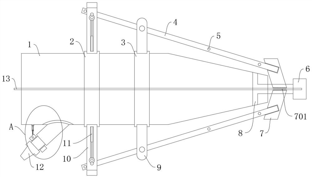
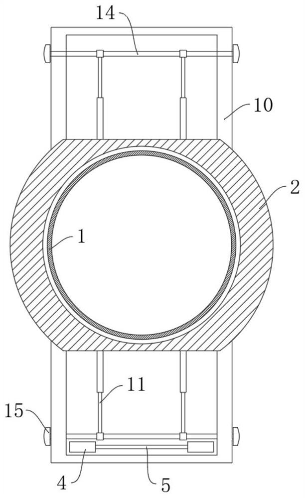
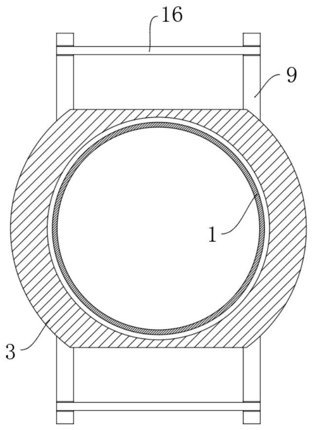
[0039]ReferenceFigure 1-6, ...


PUM


Abstract

The invention discloses a weft catching device for weaving chemical fiber filament yarn fabrics by an air jet loom. The device comprises a weft catching pipe, wherein a first pipe sleeve and a secondpipe sleeve fixedly sleeve the side wall of the weft catching pipe; two rebound mechanisms are symmetrically mounted on the first pipe sleeve; four fixing frames are symmetrically mounted on the second pipe sleeve; rotary shafts are arranged on the two fixing frames on the same side together in an inserted manner; and a weft catching mechanism is arranged on the two rotary shafts together in a rotary manner. The wefts are inserted when high-pressure air flow exists in the weft catching pipe through the weft catching mechanism and the rebound mechanisms, and when the high-pressure air flow stops, the weft catching mechanism clamps the wefts to be fixed through clamping heads without the control of electric equipment, so that the energy consumption and the cost of the device are reduced; thewefts are fixed without offsetting and sliding off through anti-skid corrugations 701 on the clamping heads; and the device is of an integrated structure, is convenient to mount, and has power and control provided by the air jet loom, so that the energy consumption and the cost of the device are reduced.

Description

Technical field[0001]The invention relates to the textile field, in particular to a weft catching device for weaving chemical fiber filament fabrics on an air jet loom.Background technique[0002]With the continuous development of modern textile technology, textile machinery is gradually upgraded from ordinary cotton and linen textile machines to air-jet looms. The high-speed air is used as the weft insertion medium to draw the weft yarns. The weft yarns need to be captured and fixed after weft insertion and beating. To avoid the draw back of the weft yarn that loses airflow after the machine stops running, causing the weft to shrink.[0003]Most of the weft catching devices of the existing air-jet looms adopt a splint-type weft catching device. The weft is inserted through a separate airflow, and then the splint is closed by a control motor to clamp and fix the weft. However, this solution requires an additional control motor to control the opening of the splint. The combination increa...

Claims


Application Information

Patent Timeline
Patent Type & Authority Patents(China)
IPC IPC(8): D03D47/30
CPCD03D47/30
Inventor 龚培强尹克明雷峰
Owner 福建宇邦纺织科技有限公司
Why Eureka
Try Eureka