Industrial Smart Camera

An intelligent camera and camera technology, applied in the field of cameras, can solve problems such as easy blocking of sight, inability to cover oil cover and cleaning, etc., to achieve the effect of convenient shooting, avoiding unclear shooting, and fulfilling the needs of fill light

Inactive Publication Date: 2021-02-26
深圳恒邦新创科技有限公司
View PDF9 Cites 0 Cited by
  • Summary
  • Abstract
  • Description
  • Claims
  • Application Information

AI Technical Summary

Problems solved by technology

[0004] The object of the present invention is to provide an industrial intelligent camera, which includes a housing, a glass cover and a camera fixing cavity. The inside of the housing is provided with a camera fixing cavity, and the camera fixing cavity is installed on the mounting seat of the camera fixing cavity. There is a glass cover, and the shell and the glass cover are connected by buckles. The shell is also equipped with a cleaning mechanism for cleaning the inner wall of the shell, so as to solve the problem that the existing device cannot clean the oil cover. When it is easy to block the line of sight

Method used


Image

  • Industrial Smart Camera
  • Industrial Smart Camera
  • Industrial Smart Camera

Examples


Embodiment 1

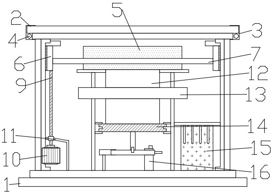
[0022] like figure 1 As shown, in the embodiment of the present invention, an industrial smart camera includes a housing 1, a glass cover 2 and a camera fixing cavity 5, the inside of the housing 1 is provided with a camera fixing cavity 5, and the camera fixing cavity 5 is installed in the camera fixing cavity On the mounting base 12, a glass cover 2 is set on the outside of the housing 1, and the housing 1 and the glass cover 2 are connected by a buckle 3, and a cleaning mechanism for cleaning the inner wall of the housing 1 is also provided in the housing 1;

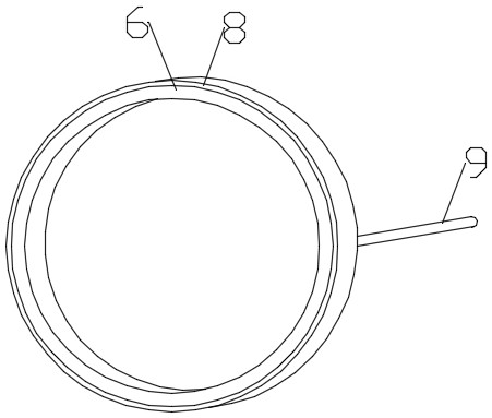
[0023] like figure 2 As shown, the cleaning mechanism includes a cleaning ring 6, a cleaning layer 8 and a screw rod 9. The cleaning ring 6 is covered with a cleaning layer 8. The cleaning layer 8 is made of a hard brush material, and the inside of the cleaning layer 8 is provided with an internal threaded hole. , the internal threaded hole is threadedly connected with a screw 9, and the inside of the cleaning ring ...

Embodiment 2

[0028] like figure 1 As shown, in the embodiment of the present invention, an industrial smart camera includes a housing 1, a glass cover 2 and a camera fixing cavity 5, the inside of the housing 1 is provided with a camera fixing cavity 5, and the camera fixing cavity 5 is installed in the camera fixing cavity On the mounting base 12, a glass cover 2 is set on the outside of the housing 1, and the housing 1 and the glass cover 2 are connected by a buckle 3, and a cleaning mechanism for cleaning the inner wall of the housing 1 is also provided in the housing 1;

[0029] like figure 2 As shown, the cleaning mechanism includes a cleaning ring 6, a cleaning layer 8 and a screw rod 9. The cleaning ring 6 is covered with a cleaning layer 8. The cleaning layer 8 is made of a hard brush material, and the inside of the cleaning layer 8 is provided with an internal threaded hole. , the internal threaded hole is threadedly connected with a screw 9, and the inside of the cleaning ring ...


PUM


Abstract

The invention discloses an industrial intelligent camera, which belongs to the technical field of cameras, and solves the problem that the existing device cannot clean the oil shielding cover, and when water vapor appears inside the cover body, it is easy to block the line of sight; its technical features include: a casing, a glass The cover and the camera fixing cavity are provided with a camera fixing cavity inside the housing, and the camera fixing cavity is installed on the mounting base of the camera fixing cavity, and the outside of the housing is provided with a glass cover, and the housing and the glass cover are connected by buckles. The housing is also provided with a cleaning mechanism for cleaning the inner wall of the housing; the embodiment of the present invention is equipped with a supplementary light assembly, and can adjust the inclination angle of the supplementary light assembly, thereby realizing the demand for supplementary light in different environments, and at the same time the cleaning mechanism The setting avoids the problem of unclear shooting caused by the atomization of the inner wall of the glass cover. At the same time, when the water vapor on the inner wall of the glass cover flows into the inner wall of the housing, the cleaning layer can also clean it, which facilitates shooting at various angles.

Description

technical field [0001] The invention relates to the technical field of cameras, in particular to an industrial intelligent camera. Background technique [0002] In industrial production and processing, it is necessary to use cameras to monitor every corner of the factory. On the one hand, it ensures the safety of products, and at the same time, it can facilitate managers to better manage production. The existing industrial cameras are very inconvenient to clean, and Due to the work of the camera, the surface of the protective cover is easy to fog, which affects the monitoring effect of the camera. [0003] Chinese patent CN209250745U discloses a camera assembly used for double-sided product defect detection and equipped with an oil shield, including a snap-in base with an inverted U-shaped structure, and the snap-in base is snapped on the frame of the machine tool body, snapped There are locking bolts on the longitudinal side of the base, and a support rod is fixed vertical...

Claims


Application Information

Patent Timeline
Patent Type & Authority Patents(China)
IPC IPC(8): H04N5/225
CPCH04N23/52H04N23/56H04N23/51
Inventor 赵崇伟李军王久宝
Owner 深圳恒邦新创科技有限公司
Why Eureka
Try Eureka