


Quick Research
Generate reliable direction feasibility study reports for your R&D in just a few steps.

Technical Q&A
Discover and master advanced knowledge NOW. Basics, ideas, possibilities, all at once.

Find Solutions
As an expert in R&D theories, this can generate solutions to your technical problems instantly.

Evaluate Feasibility
Analyze your overall solution with one click, know your potential R&D risks in advance.

Monitor Landscape
Get weekly tech updates, stay abreast of the latest tech innovations and key insights.
Industrial intelligent camera
A smart camera and camera technology, applied in the field of cameras, can solve problems such as easy to block the line of sight, unable to clean the oil cover, etc., to achieve the effect of convenient shooting, avoiding unclear shooting, and realizing the demand for supplementary light
- Summary
- Abstract
- Description
- Claims
- Application Information
AI Technical Summary
Problems solved by technology
Method used
Image

Examples
Embodiment 1
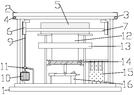
[0022] Such as figure 1 As shown, in the embodiment of the present invention, an industrial smart camera includes a housing 1, a glass cover 2 and a camera fixing cavity 5. The housing 1 is provided with a camera fixing cavity 5, and the camera fixing cavity 5 is installed in the camera fixing cavity On the mounting seat 12, a glass cover 2 is sleeved on the outside of the housing 1, and the housing 1 and the glass cover 2 are connected by a buckle 3. The housing 1 is also provided with a cleaning mechanism for cleaning the inner wall of the housing 1;
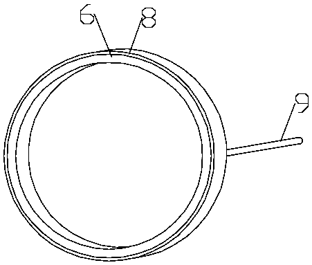
[0023] Such as figure 2 As shown, the cleaning mechanism includes a cleaning ring 6, a cleaning layer 8 and a screw 9. The cleaning ring 6 is sheathed with a cleaning layer 8. The cleaning layer 8 is made of hard brush material, and the cleaning layer 8 is provided with internal threaded holes. , The internal threaded hole is threadedly connected with a screw 9, and the cleaning ring 6 is also provided with an inner support ring ...
Embodiment 2
[0028] Such as figure 1 As shown, in the embodiment of the present invention, an industrial smart camera includes a housing 1, a glass cover 2 and a camera fixing cavity 5. The housing 1 is provided with a camera fixing cavity 5, and the camera fixing cavity 5 is installed in the camera fixing cavity On the mounting seat 12, a glass cover 2 is sleeved on the outside of the housing 1, and the housing 1 and the glass cover 2 are connected by a buckle 3, and a cleaning mechanism for cleaning the inner wall of the housing 1 is also provided in the housing 1;
[0029] Such as figure 2 As shown, the cleaning mechanism includes a cleaning ring 6, a cleaning layer 8 and a screw 9. The cleaning ring 6 is sheathed with a cleaning layer 8. The cleaning layer 8 is made of hard brush material, and the cleaning layer 8 is provided with internal threaded holes. , The internal threaded hole is threadedly connected with a screw 9, and the cleaning ring 6 is also provided with an inner support rin...
PUM
 Abstract
Description
Claims
Application Information
 - R&D Engineer
- R&D Manager
- IP Professional
- Industry Leading Data Capabilities
- Powerful AI technology
- Patent DNA Extraction
Browse by: Latest US Patents, China's latest patents, Technical Efficacy Thesaurus, Application Domain, Technology Topic, Popular Technical Reports.
© 2024 PatSnap. All rights reserved.Legal|Privacy policy|Modern Slavery Act Transparency Statement|Sitemap|About US| Contact US: help@patsnap.com