
Closed cooling structure of a wind power generator

A technology for wind turbines and cooling structures, which is applied in the shape/pattern/structure of magnetic circuit, cooling/ventilation device, electromechanical device, etc., and can solve the problems of underutilization of cooling capacity, uneven temperature around the motor, and increased maximum temperature. , to achieve the effect of making full use of cooling capacity, reducing circumferential temperature difference and reducing motor power

Active Publication Date: 2020-12-04
CRRC XIAN YONGE JIELI WIND ENERGY CO LTD
View PDF7 Cites 0 Cited by
  • Summary
  • Abstract
  • Description
  • Claims
  • Application Information

AI Technical Summary

Problems solved by technology

[0006] The purpose of the present invention is to provide a closed cooling structure for wind power generators, which solves the problem that the air in and out of the rotor ventilation structure of the existing permanent magnet wind power generators is usually one or two air outlets corresponding to the fan, or corresponding to the cooler. One or two seals lead to uneven temperature around the motor, large temperature difference, high maximum temperature rise, and insufficient cooling capacity

Method used


Image

  • Closed cooling structure of a wind power generator
  • Closed cooling structure of a wind power generator
  • Closed cooling structure of a wind power generator

Examples


Embodiment Construction

[0037] The present invention is described in further detail below in conjunction with accompanying drawing:

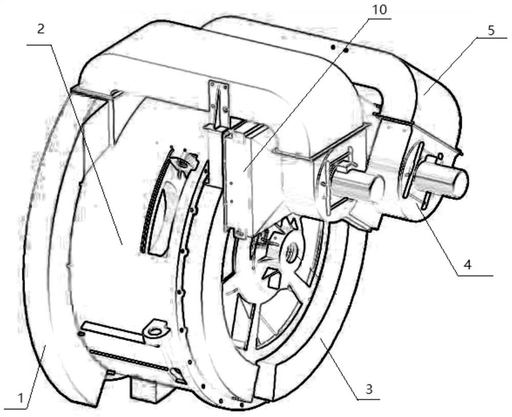
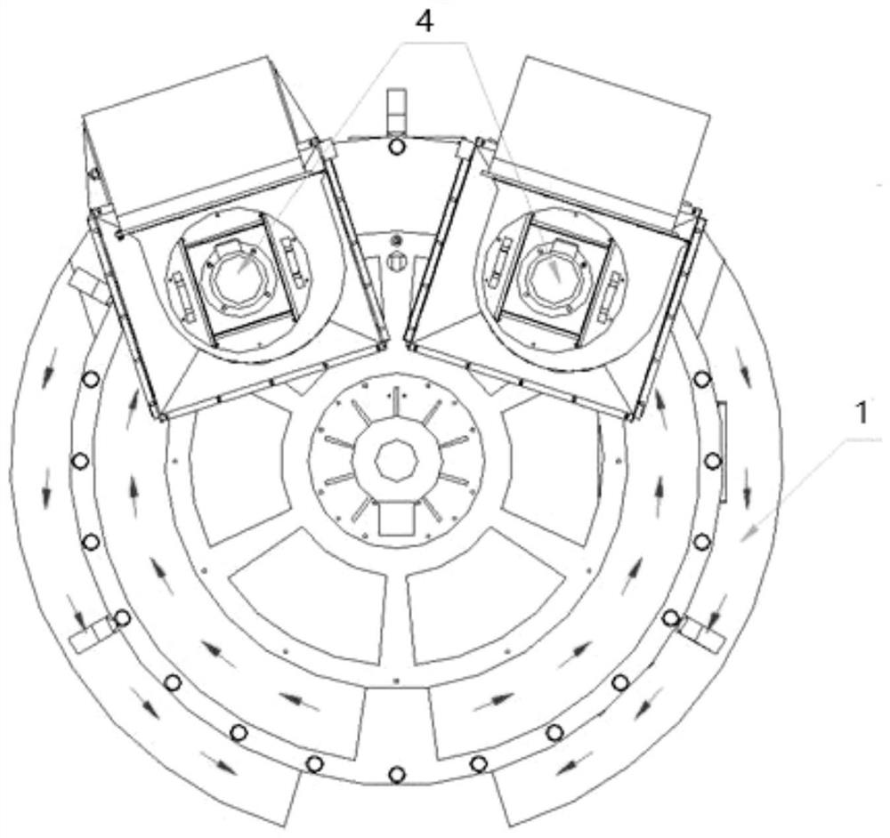
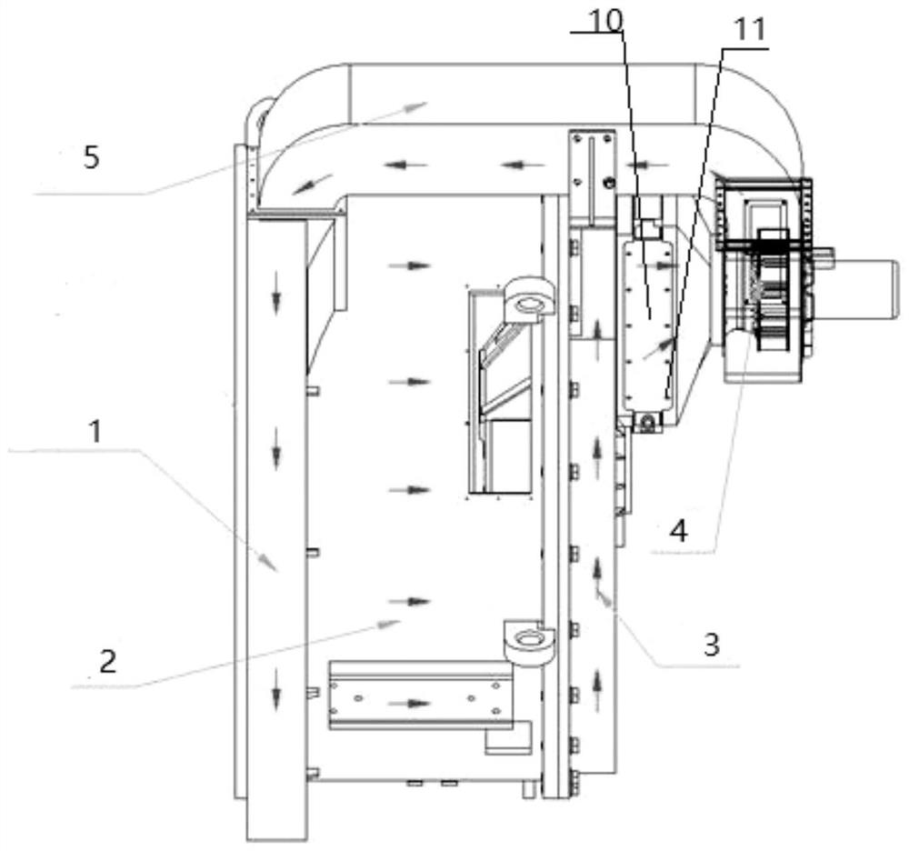
[0038] Such as Figure 1-3 As shown, a closed cooling structure of a wind power generator includes, from left to right, an air inlet air collection channel 1 , a machine base 2 , an air outlet air collection channel 3 and a fan 4 .

[0039] The frame 2 is provided with a transmission direction and a non-transmission direction.

[0040] The air intake duct 1 is located in the transmission direction, and the air intake duct 1 and the base 2 are fixed by bolts.

[0041] The air outlet air collection duct 3 is located in the non-transmission direction, and the air outlet air collection duct 3 and the machine base 2 are fixed by bolts.

[0042] The air-inlet air-collecting channel 1 and the air-outlet air-collecting channel 3 are respectively arranged in a semicircle to facilitate the circulation direction of the wind.

[0043] An air inlet duct 5 is arranged between the...


PUM


Abstract

The present invention belongs to the field of wind turbines, and relates to a wind turbine closed cooling structure, comprising in sequence, from left to right, an inlet air collection channel, a machine base, an outlet air collection channel and a fan; the inlet air collection channel is positioned on a transmission direction, and the inlet air collection channel is connected to the machine base; the outlet air collection channel is positioned on a non-transmission direction, and the outlet air collection channel is connected to the machine base; an inlet air channel is disposed between the inlet air collection channel and the outlet air collection channel, one end of the inlet air channel being in communication with the inlet air collection channel, and another end of the inlet air channel being in communication with the fan; the present structure is characterized by a low-air resistance structure of a rotor part, and air inlet and outlet openings being as uniformly arranged as possible; the present air passage structure can prevent oil vapor in a nacelle from entering a motor; the low-air resistance rotor structure can effectively cool a bearing, and can also lower the power for a forced cooling drive motor and increase the cooling capacity of a cooler; the uniform air inlet and outlet structures can ensure a more uniform temperature for the motor, lowering winding heating and increasing motor power.

Description

technical field [0001] The invention belongs to the field of wind power generators, in particular to a closed cooling structure for wind power generators. Background technique [0002] As a clean and renewable energy source, wind power has attracted more and more attention from all over the world due to its good environmental and economic benefits. [0003] Among the many types of wind turbines, the compact permanent magnet wind turbine has become the representative of the new generation of wind turbines because of its light weight, small size, low cost, high efficiency, and low maintenance. [0004] The existing permanent magnet wind turbine structure includes a rotor ventilation structure. The rotor ventilation structure usually flows axially through the air gap between the rotors and the gap between the rotor magnetic poles. The air entering and exiting the fan usually corresponds to one or two vents. [0005] However, the air in and out of the rotor ventilation structur...

Claims


Application Information

Patent Timeline
Patent Type & Authority Patents(China)
IPC IPC(8): H02K9/04H02K5/20H02K5/00H02K1/30H02K9/19
CPCH02K1/30H02K5/00H02K5/20H02K9/04H02K9/19
Inventor 张晋军俞文斌王文庆尤佰朋次元平
Owner CRRC XIAN YONGE JIELI WIND ENERGY CO LTD
Learn More