Assembling method of combined bearing
An assembly method and combined bearing technology, applied to bearing components, shafts and bearings, mechanical equipment, etc., can solve the problems affecting the vibration and noise performance of the bearing, such as rotation accuracy, temperature rise, vibration increase, and the inability to adjust the preload, etc., to achieve Improve the efficiency of assembly, ensure cleanliness, and the effect of high-efficiency installation
- Summary
- Abstract
- Description
- Claims
- Application Information
AI Technical Summary
Problems solved by technology
Method used
Image
Examples
Embodiment 1
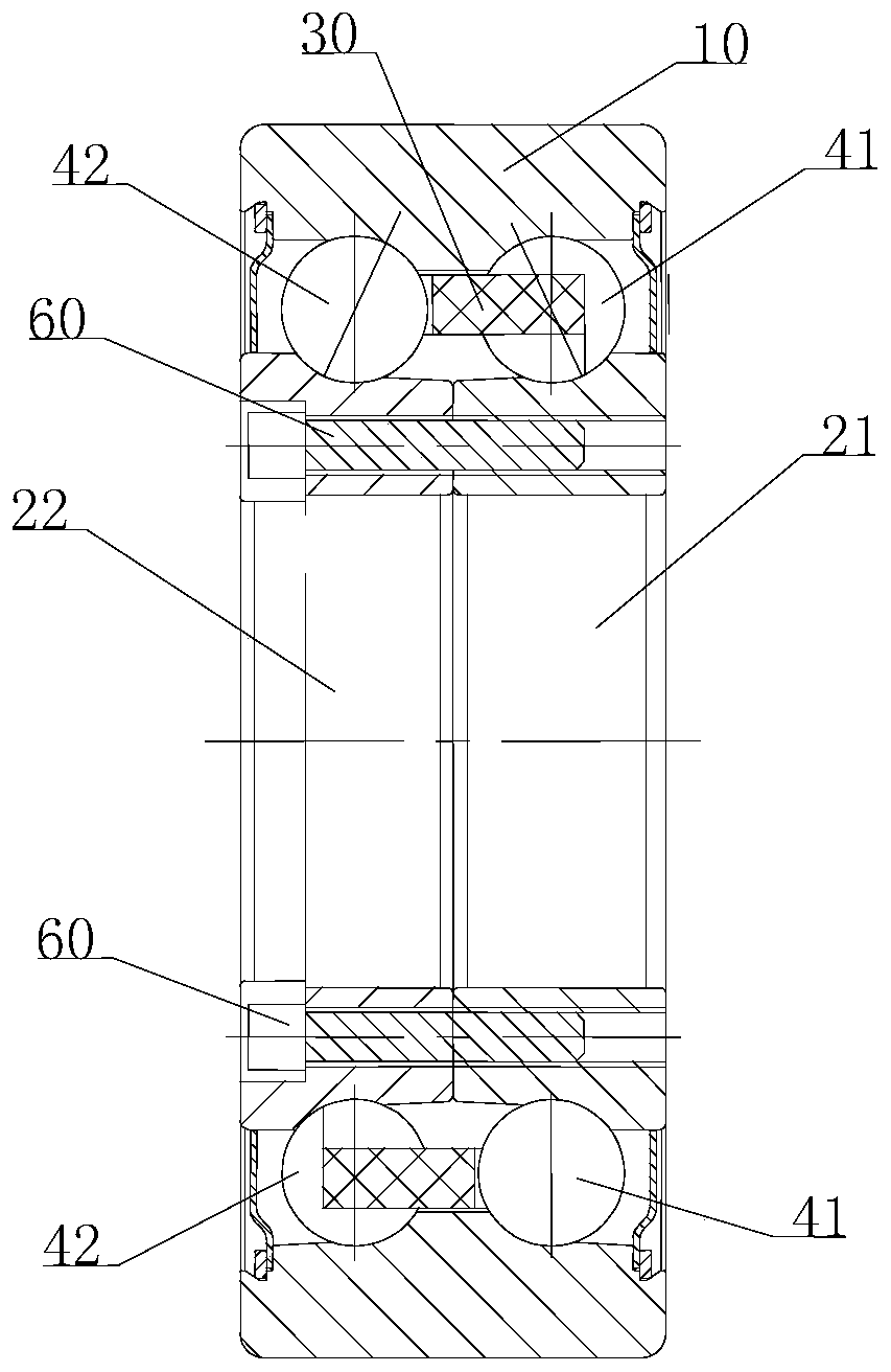
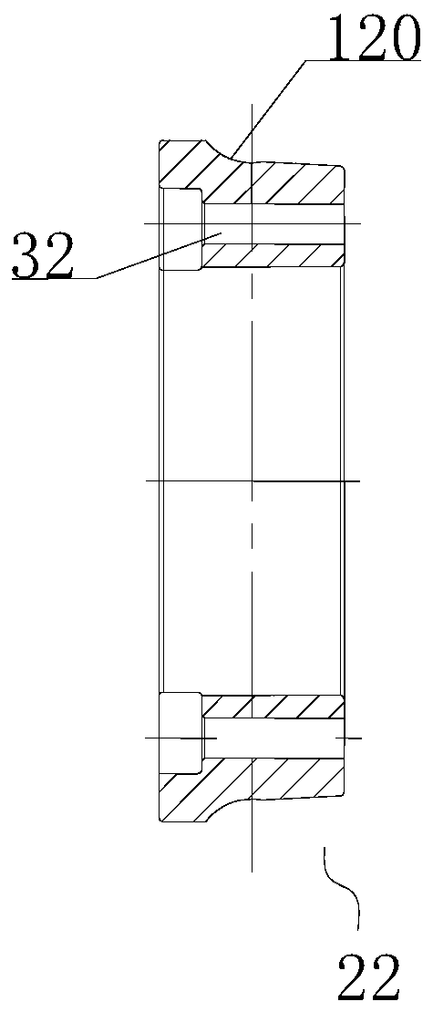
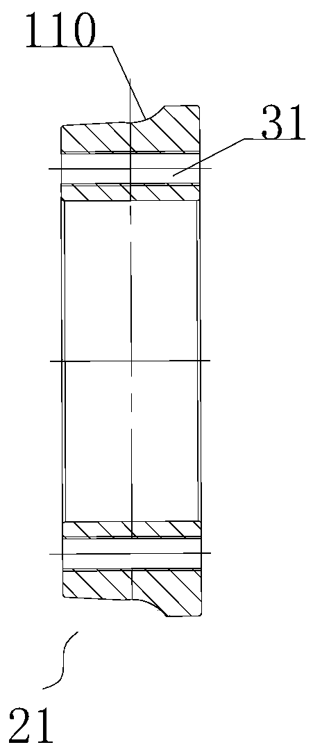
[0038] A combined bearing such as Figure 1-5 As shown, it includes a bearing outer ring 10, a bearing inner ring and a cage 30, the bearing inner ring is rollingly connected with the bearing outer ring 10, and the bearing frame 30 is installed between the bearing outer ring 10 and the bearing inner ring, There are two bearing inner rings, namely a first bearing inner ring 21 and a second bearing inner ring 22, and the first bearing inner ring 21 and the second bearing inner ring 22 are installed side by side in the bearing outer ring 10 , the first bearing inner ring 21 and the second bearing inner ring 22 are detachably and fixedly connected by a connecting piece. In this embodiment, the first bearing inner ring 21 is provided with first installation holes 31, and the first installation holes 31 are circumferentially distributed on the first bearing inner ring 21, and the second bearing inner ring The second installation holes 32 are opened on the second bearing inner ring ...
Embodiment 2
[0043] A bearing assembly mold, used for the assembly of the combined bearing described in Embodiment 1, the assembly mold includes a first assembly mold 1 and a second assembly mold 2, such as Figure 6-8 As shown, the outer diameters of the first assembly mold 1 and the second assembly mold 2 are the same, and they are a pair of molds. The first assembly mold 1 includes a base 100 and a steel ball support 111 , the steel ball support 111 is integrated with the base 100 , and the steel ball support 111 protrudes from the middle of the base 100 . The base 100 is provided with a circularly distributed first positioning groove 101 and a first mounting platform 102, the two sides of the first positioning groove 101 are platform structures, and the height of the outer platform is greater than the height of the inner platform, so as to better To support the bearing outer ring 10 and the cage 30 placed in the first assembly die 1 , the outer platform is the platform on the side away...
Embodiment 3
[0046] A method for assembling combined bearings, such as Figure 9-15 shown, including the following steps:
[0047] Step 1, place the outer ring of the bearing and the cage respectively on the first positioning groove and the first installation platform of the first assembly mold placed horizontally, and put the first steel balls into the first accommodation groove of the cage to form The first component is used to lift and position the outer ring of the bearing, the cage and the first steel balls installed in the first channel by using the first assembly mold;
[0048] Step 2, install the first bearing inner ring into the first assembly formed in step 1, the first bearing inner ring partly protrudes into the center hole, the first stop on the first bearing inner ring The groove is matched with the first steel ball to complete the assembly of the first row of steel balls and obtain the first assembly;
[0049] Step 3, turning the first assembly over 180 degrees as a whole,...
PUM
 Abstract
Description
Claims
Application Information
 - R&D Engineer
- R&D Manager
- IP Professional
- Industry Leading Data Capabilities
- Powerful AI technology
- Patent DNA Extraction
Browse by: Latest US Patents, China's latest patents, Technical Efficacy Thesaurus, Application Domain, Technology Topic, Popular Technical Reports.
© 2024 PatSnap. All rights reserved.Legal|Privacy policy|Modern Slavery Act Transparency Statement|Sitemap|About US| Contact US: help@patsnap.com


