
Travelling type hull cracking leakage stop device

A walking device and walking-type technology, which is applied to the safety of ships, transportation and packaging, ships, etc., can solve the problems of inconvenient plugging operation and inconvenient plugging operation of ship crawler-type quick-blocking boards, and achieve convenient operation, The effect of high plugging efficiency

Active Publication Date: 2020-01-24
ZHEJIANG MARINE DEV RES INST
View PDF6 Cites 0 Cited by
  • Summary
  • Abstract
  • Description
  • Claims
  • Application Information

AI Technical Summary

Problems solved by technology

The ship's crawler-type quick-blocking board in this application puts the ship's crawler-type quick-stopping board into the cracks of the hull through a dispenser, lays the quick-stopping board, and adsorbs the quick-stopping board on the outer wall of the hull through thin and strong magnetic sheets and water pressure , to seal holes and cracks. In this way, although the purpose of sealing holes and cracks can be achieved, it is inconvenient to put in and plug leaks of the ship’s crawler-type quick-blocking plate in this application. Specifically, in this application, the ship The crawler-type quick-blocking plate is rolled on the drum before being put in, and put in through the dispenser. The dispenser has a cable and a connecting rod. When plugging, it is not only necessary to manually operate the connecting rod of the dispenser to move the dispenser and the ship on the drum. The crawler-type quick-blocking plate also needs to manually operate the cable of the dispenser to control the release roller to realize the plugging work of the leak point, which has the problem of inconvenient plugging operation

Method used


Image

  • Travelling type hull cracking leakage stop device
  • Travelling type hull cracking leakage stop device
  • Travelling type hull cracking leakage stop device

Examples


specific Embodiment 1

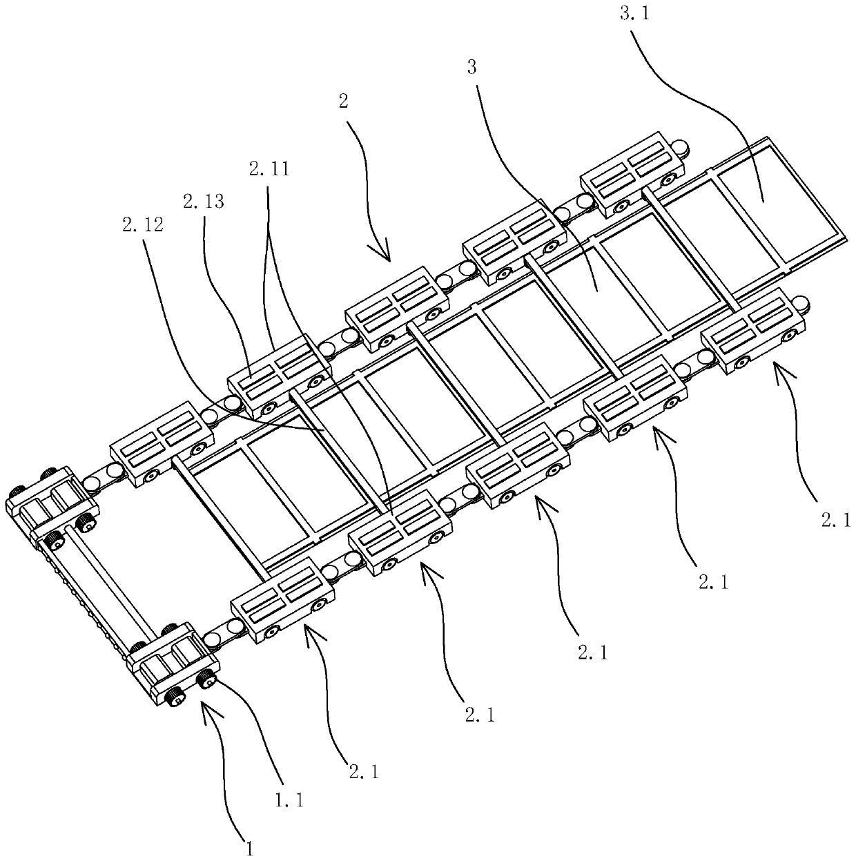
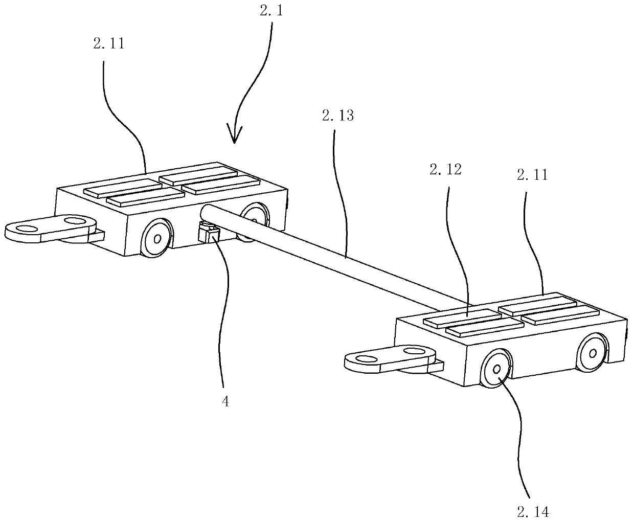
[0032] Specific embodiment one: as figure 1 , figure 2 As shown, a walking type hull crack plugging device includes a walking device and a magnetic sealing belt device 3 . The traveling device comprises a driving car 1, a driven car group 2 connected to the driving car and a sealing tape installation device for installing a magnetic sealing tape device.

[0033] Such as figure 1 As shown, the driving car 1 includes several magnetic wheels 1.1, the driving car is adsorbed on the outer wall surface of the hull through the magnetic wheels, and walks on the outer wall surface of the hull through the magnetic wheels. The motor vehicle also includes a waterproof motor for driving the magnetic wheel to rotate, and the waterproof motor drives the magnetic wheel to rotate so that the driving vehicle can walk on the outer wall surface of the hull. In this embodiment, the magnetic wheel includes a wheel and a plurality of magnets that are evenly distributed on the tread of the wheel ...


PUM


Abstract

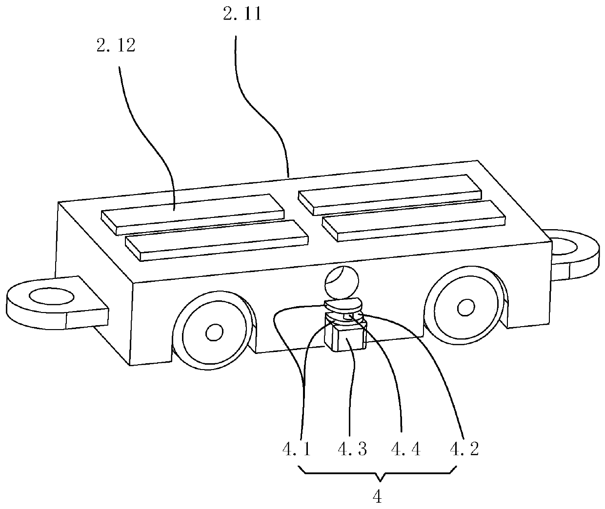
The invention discloses a traveling type hull cracking leakage stop device, and aims to provide the travelling type hull cracking leakage stop device which can utilize water pressure to perform leakage stop, is convenient in leakage stop operation and is high in leakage stop efficiency. The travelling type hull cracking leakage stop device comprises a travelling device and a magnetic sealing beltdevice, wherein the travelling device comprises a drive vehicle, a driven vehicle group connected to the drive vehicle and a sealing belt mounting device for mounting a magnetic sealing belt device, the drive vehicle is adsorbed on the outer wall surface of a hull through a magnetic wheel, the driven vehicle group comprises a plurality of driven vehicles which are sequentially hinged and connected, and the driven vehicles are adsorbed on the outer wall surface of the hull through a vehicle magnetic part; the sealing belt mounting device comprises a plurality of mounting assemblies which are arranged on the driven vehicles in a one-to-one correspondence mode, and each mounting assembly comprises mounting parts which are arranged on left and right driven vehicle bodies of the driven vehiclein the one-to-one correspondence mode; and the magnetic sealing belt device comprises a rubber sealing belt and a sealing belt magnetic part arranged on the rubber sealing belt.

Description

technical field [0001] The invention relates to a plugging device, in particular to a walking type leak plugging device for hull cracks. Background technique [0002] During the voyage of the ship, the hull may have cracks or holes due to collisions and other reasons, and it is necessary to plug the cracks or holes in the hull in time, otherwise the hull will easily cause safety problems such as tilting the hull or even sinking due to water pouring into the cabin; but Since the underwater leak plugging needs to overcome the water pressure, the current underwater leak plugging of the hull usually has the problems of difficult operation and low efficiency. [0003] In order to solve this problem, some inventors have made improvements. For example, Chinese Patent Publication No. CN102320359B, the name of the invention is a ship crawler-type quick-blocking plate. Arrange and connect thin plates; two adjacent thin plates are hinged to form a crawler form as a whole; one side of ...

Claims


Application Information

Patent Timeline
Patent Type & Authority Applications(China)
IPC IPC(8): B63B43/16
CPCB63B43/16
Inventor 季建徐娇周枫徐颖俊林传颂於斌杨凯盛
Owner ZHEJIANG MARINE DEV RES INST
Learn More