
Multi-section machining special pipeline cutting device

A pipe cutting and special technology, applied in the direction of positioning device, feeding device, metal processing equipment, etc., can solve the problems of low work efficiency, high labor intensity, low precision, etc., to reduce the scattering of waste, facilitate multi-stage processing, improve The effect of work efficiency

Inactive Publication Date: 2020-01-24
江苏新泰隆管件有限公司
View PDF9 Cites 10 Cited by
  • Summary
  • Abstract
  • Description
  • Claims
  • Application Information

AI Technical Summary

Problems solved by technology

[0003] The purpose of the present invention is to provide a special pipe cutting device for multi-stage processing, to solve the problem of high labor intensity and low precision of manual cutting proposed in the above background technology, but the existing mechanical device cutting, because the position of the cutting knife is fixed, during processing It is necessary to constantly adjust the cutting pipe. Each time you adjust, you need to continuously loosen the fixed pipe and then fix it at the designated position. The operation is more troublesome and takes a certain amount of time. The work efficiency is low, and the cutting knife is worn for a long time. Replacement Inconvenient question

Method used


Image

  • Multi-section machining special pipeline cutting device
  • Multi-section machining special pipeline cutting device
  • Multi-section machining special pipeline cutting device

Examples


Embodiment Construction

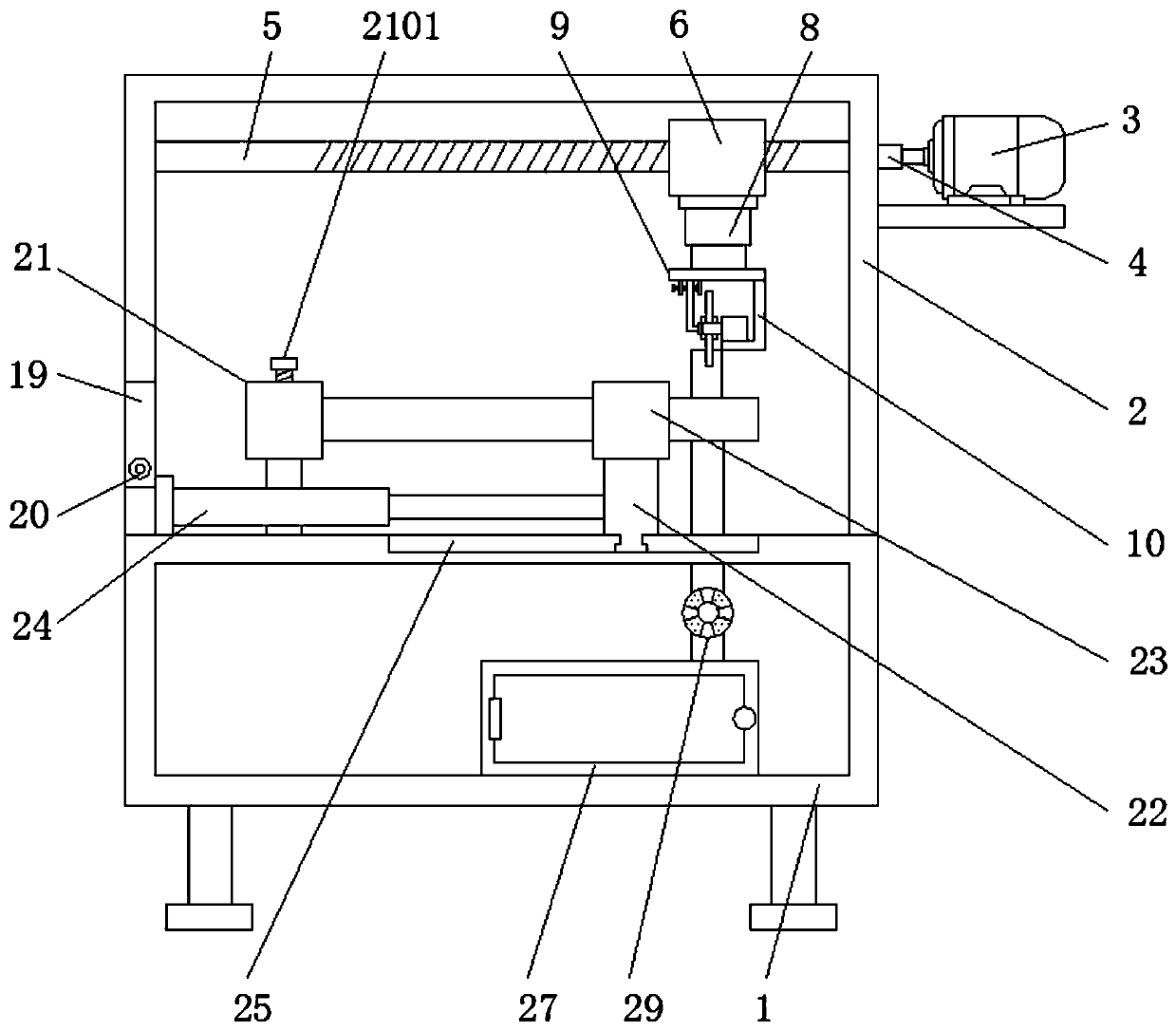
[0028] The following will clearly and completely describe the technical solutions in the embodiments of the present invention with reference to the accompanying drawings in the embodiments of the present invention. Obviously, the described embodiments are only some, not all, embodiments of the present invention. Based on the embodiments of the present invention, all other embodiments obtained by persons of ordinary skill in the art without making creative efforts belong to the protection scope of the present invention.

[0029] see Figure 1-8 , the present invention provides a technical solution: a special pipe cutting device for multi-stage processing, such as figure 1 with figure 2 As shown, the upper surface of the device body 1 is provided with a support 2, and the right side of the support 2 is provided with a first motor 3, the first motor 3, the first rotating rod 4 and the threaded rod 5 form a rotating mechanism, and the threaded rod 5 and The moving blocks 6 are ...


PUM


Abstract

The invention discloses a multi-section machining special pipeline cutting device. The device comprises a device body and a groove, a first motor is connected with a first rotating rod, the groove isarranged on the left side wall of a supporting frame, a first rotating rod is rotationally connected to the inner side wall of the groove, a first fixed frame is arranged on the right side of the groove, the first fixed frame is arranged on the upper surface of the device body, the upper surface of the device body is provided with a sliding groove, the upper surface of the device body is connectedwith the lower end of a supporting plate through the sliding groove, a second fixed frame is arranged at the upper end of the supporting plate, and a first hydraulic telescopic rod is arranged on theleft side of the supporting plate. According to the multi-section machining special pipeline cutting device, the first rotating rod and a threaded rod can be driven to rotate through the first motor,so that a moving block moves transversely on the threaded rod, the position of a cutting knife can be changed, cutting work on different positions of the pipeline is achieved, the multi-section machining of the pipeline is convenient, the position of the pipeline does not need to be adjusted repeatedly, and the working efficiency is improved.

Description

technical field [0001] The invention relates to the related technical field of special pipeline processing, in particular to a special pipeline cutting device for multi-stage processing. Background technique [0002] Special pipelines are mainly used in the fields of gas pipelines and chemical pipelines. Special pipelines often use cutting devices during processing. Nowadays, special pipelines can be cut by mechanical cutting and manual cutting. Manual cutting is labor-intensive and low-precision, but now Some mechanical devices cut, because the position of the cutting knife is fixed, the cutting pipe needs to be adjusted continuously during processing, and the fixed pipe needs to be loosened continuously during each adjustment, and then fixed at the designated position, the operation is more troublesome, and the work Efficiency is low, and cutting knife wears and teares after using for a long time, and replacement is inconvenient. Contents of the invention [0003] The p...

Claims


Application Information

Patent Timeline
IPC IPC(8): B23D79/00B23Q11/00B23Q3/06B23Q5/26B23Q1/25
CPCB23D79/00B23Q1/25B23Q3/064B23Q5/26B23Q11/0046
Inventor 李正华金龙夏誉容
Owner 江苏新泰隆管件有限公司
Learn More