Electromagnetic actuator

An actuator and electromagnetic technology, applied in the direction of circuits, magnets, magnetic objects, etc., can solve problems such as strong wear of the core, damage to the electromagnetic actuator, etc.

Pending Publication Date: 2020-01-21
SVM SCHULTZ VERW
View PDF6 Cites 0 Cited by
  • Summary
  • Abstract
  • Description
  • Claims
  • Application Information

AI Technical Summary

Problems solved by technology

This is accompanied by a corresponding mechanical load on the core, which leads to strong wear of the core or damage to the electromagnetic actuator

Method used


Image

  • Electromagnetic actuator
  • Electromagnetic actuator
  • Electromagnetic actuator

Examples


Embodiment Construction

[0054] In the figures, elements that are identical or correspond to one another are marked with the same reference numerals and are therefore not described again unless it is useful. The disclosure content contained in the entire description can be transferred sensibly to the same parts with the same reference signs or the same component designations. The position indications selected in the description, such as top, bottom, side, etc., refer to the directly described and shown figures and should be transferred accordingly to the new position if the position changes. position. Furthermore, individual features and feature combinations in the various exemplary embodiments shown and described can themselves also form independent, inventive or inventive solutions.

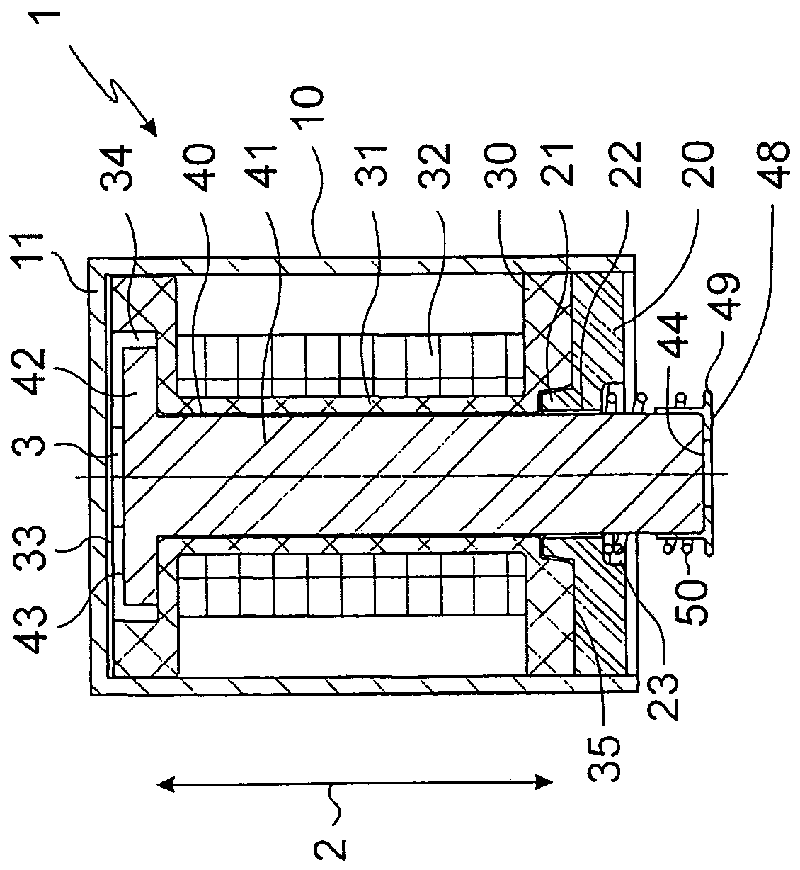
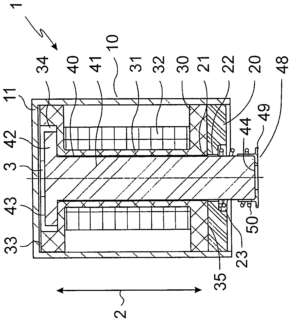
[0055] Figure 1a and 1b An electromagnetic actuator 1 according to one embodiment of the invention is shown, which is connected to a valve part of a valve, for example via a plunger, for actuating the valve. The ac...


PUM


Abstract

The invention relates to an electromagnetic actuator, in particular for actuating a valve. The electromagnetic actuator includes a housing with a cover wall and a magnet yoke opposite the cover wall.The actuator also comprises a coil body which is arranged in the housing between the cover wall and the magnet yoke and is provided with a tubular section, wherein a coil winding is arranged on the outer side of the tubular section; and an armature movably arranged in the tubular section along the movement direction.

Description

technical field [0001] The invention relates to an electromagnetic actuator, in particular an electromagnetic actuator for actuating a valve. Background technique [0002] Electromagnetic actuators generally consist of a coil and a movable armature. Coils and armatures are important parts of the electromagnetic components of electromagnetic actuators. A current is applied to the coil to move the armature, thereby generating a magnetic field in which the armature is subjected to an accelerated magnetic force. [0003] In detail, the electromagnetic actuator comprises: at least one housing with a cover wall and a yoke opposite to the cover wall; a coil body arranged in the housing between the cover wall and the yoke Between and there is a tubular section; a coil winding arranged on the outside of the tubular section; and an armature arranged movably in the tubular section in the direction of movement. [0004] For actuating the valve, the electromagnetic actuator and the va...

Claims


Application Information

Patent Timeline
Patent Type & Authority Applications(China)
IPC IPC(8): H02K33/02
CPCH02K33/02H01F7/1623H01F7/088
Inventor P·维德曼
Owner SVM SCHULTZ VERW
Why Eureka
Try Eureka