Charging circuit and charging system

A charging circuit and technology to be charged, applied in battery circuit devices, charging/discharging current/voltage regulation, charging stations, etc., can solve problems such as inconvenient charging, and achieve the effect of convenient charging and flexible charging methods

Active Publication Date: 2020-01-21
GUANGZHOU XAIRCRAFT TECH CO LTD
View PDF7 Cites 2 Cited by
  • Summary
  • Abstract
  • Description
  • Claims
  • Application Information

AI Technical Summary

Problems solved by technology

[0005] The purpose of this application is to provide a charging circuit and charging system to solve the problem of inconvenient charging in the prior art

Method used


Image

  • Charging circuit and charging system
  • Charging circuit and charging system
  • Charging circuit and charging system

Examples


no. 1 example

[0033] As mentioned in the background art, the current methods for optimizing the continuous operation time of agricultural drones are mainly to increase the battery life and directly charge on-site. However, as for the direct charging method at the job site, on the one hand, due to limited rural conditions, imperfect grid coverage, or unstable voltage, it cannot provide stable city power, and the rate of sequential charging is slow. On the other hand, the way to charge agricultural drones on the job site is to use a fixed port for charging, and the charging method is not flexible. For example, users cannot charge multiple drones through the charging circuit.

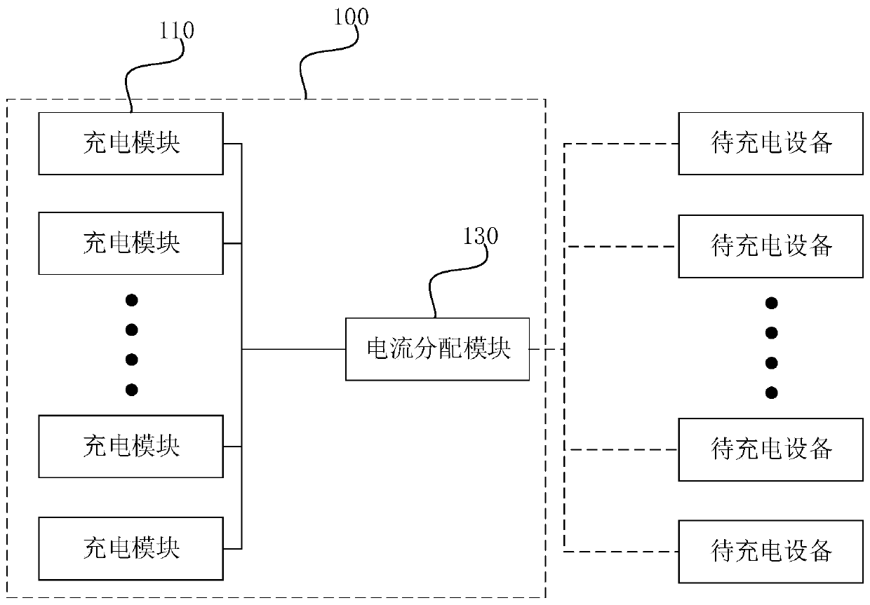
[0034] In view of this, the present application provides a charging circuit, by setting at least two charging modules, and controlling the working state of the current distribution module through a CPU (central processing unit, central processing unit), and at the same time setting multiple current distribution modules Th...

no. 2 example

[0079] The present application also provides a charging system. The charging system includes a generator and the charging circuit as described in the first embodiment, the generator is electrically connected to the charging circuit, and the charging circuit is used to provide electrical energy generated by the generator to the device to be charged. Recharge. Since the circuit structure and working principle of the charging circuit have already been described in detail in the first embodiment of the present application, this application will not be repeated here.

[0080] In summary, the present application provides a charging circuit and a charging system. The charging circuit includes a current distribution module and at least two charging modules. The at least two charging modules are electrically connected to the current distribution module. The current distribution module includes multiple outputs. Port, where the current distribution module is used to connect one or more dev...


PUM


Abstract

The application provides a charging circuit and a charging system, and relates to the technical field of drone charging. The charging circuit includes a current distribution module and at least two charging modules. The at least two charging modules are electrically connected to the current distribution module. The current distribution module includes multiple output ports. The current distribution module is configured to be connected to one or more devices to be charged through the output ports. The at least two charging modules are configured to supply power to the devices to be charged through the current distribution module. Each charging module includes a CPU. The CPU is electrically connected to the current distribution module. The CPU is configured to control the working status of the current distribution module to adjust the charging mode of the charging circuit. The charging circuit and charging system provided in the present application have the advantages of flexible charging modes and convenient charging.

Description

Technical field [0001] This application relates to the technical field of unmanned aerial vehicle charging, in particular to a charging circuit and a charging system. Background technique [0002] Agricultural drones are a kind of drones used to improve the efficiency of agricultural production, such as the currently widely used plant protection drones. [0003] When agricultural drones are operating on site, the continuous operating time has a greater impact on the efficiency of the operation. In order to optimize the continuous operation time, the currently commonly used method is to increase the battery life time, or to charge the drone on the job site. [0004] At present, the method of charging agricultural drones on the job site is to use a fixed port for charging. This charging method is not flexible, and the charging time is long, and there is a problem of inconvenient charging during actual use. Summary of the invention [0005] The purpose of this application is to provide...

Claims


Application Information

Patent Timeline
Patent Type & Authority Applications(China)
IPC IPC(8): H02J7/00B60L53/30
CPCH02J7/007B60L53/30B60L2200/10B64U10/00Y02T10/70Y02T10/7072Y02T90/12
Inventor 康振华于江涛
Owner GUANGZHOU XAIRCRAFT TECH CO LTD
Why Eureka
Try Eureka