Electrical stimulation anti-fatigue system and control method

An electric stimulation and anti-fatigue technology, which is applied in the direction of control devices, devices that cause changes in the perception state, hypnosis devices, etc., can solve the problems of driver drug resistance, driver physical damage, and inconvenient application, and improve the accuracy of fatigue detection. Improve control accuracy and facilitate installation

Active Publication Date: 2020-01-21
CHANGAN UNIV
View PDF6 Cites 2 Cited by
  • Summary
  • Abstract
  • Description
  • Claims
  • Application Information

AI Technical Summary

Problems solved by technology

The existing incentive methods mostly use buzzer (sound stimulation), light alarm (light stimulation), vibrator (vibration stimulation), or mainly rely on the driver's own consciousness and rely on refreshing drugs or drinks to stimulate the driver, so that the driving Drivers stay awake, but the effect is not good. For long-term use of refreshing food, it will not only cause physical damage to the driver, but even cause the driver’s resistance to drugs; will decline, so the existing anti-fatigue devices have the disadvantages of insufficient reminders and limited prevention, which lead to the shortcomings of not being able to keep the driver awake.
In addition, the existing anti-fatigue devices, such as anti-fatigue glasses and anti-fatigue seats, all need to be worn by the driver or have a huge change to the device in the car, so it is extremely inconvenient to apply to existing vehicles

Method used


Image

  • Electrical stimulation anti-fatigue system and control method
  • Electrical stimulation anti-fatigue system and control method
  • Electrical stimulation anti-fatigue system and control method

Examples


Embodiment Construction

[0046] The present invention is described in further detail below in conjunction with accompanying drawing:

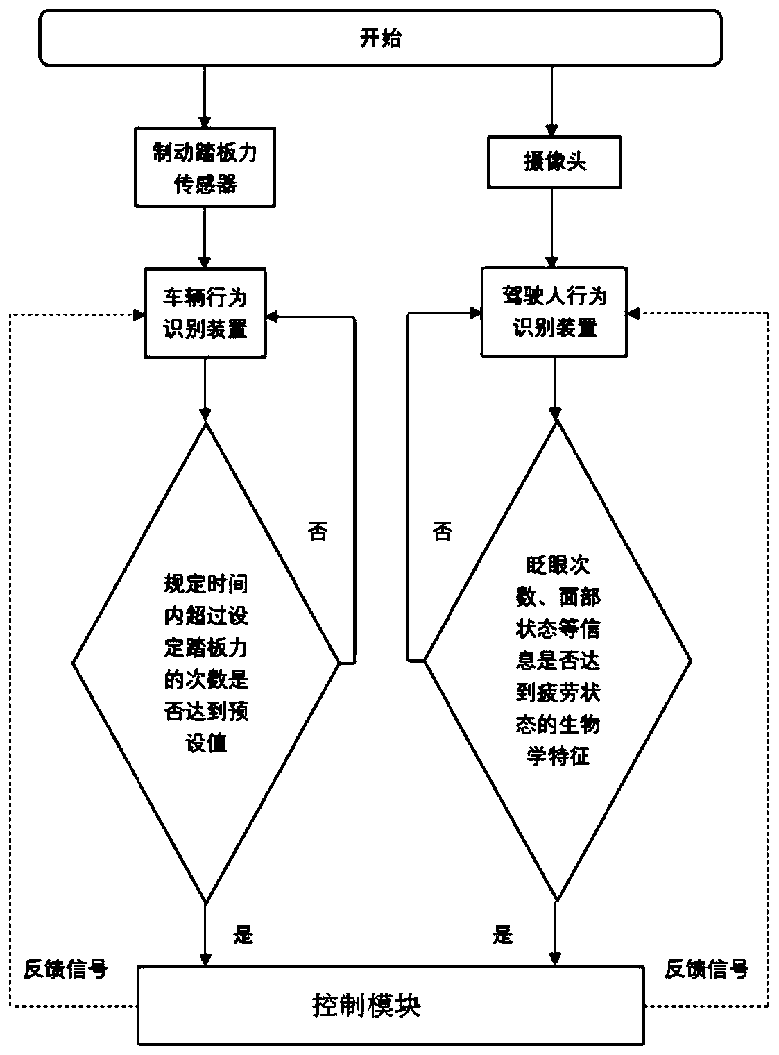
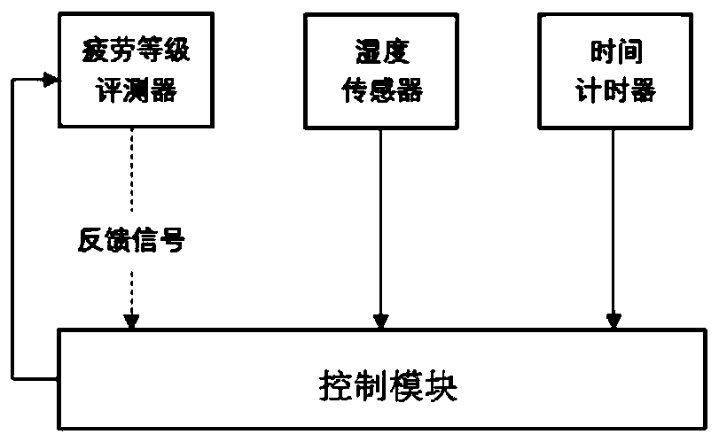
[0047] like Figure 1-Figure 4 As shown, an electrical stimulation anti-fatigue system includes a fatigue state detection module, a control module and an electric stimulation module. The fatigue state detection module is used to detect the fatigue state of the driver and feed back the detected fatigue state information of the driver to the control module. The control module matches the control signal according to the received driver fatigue state information, and transmits the control signal to the electric stimulation module, which is arranged on the driver's seat, and the electric stimulation module generates stimulation current according to the received control signal.

[0048] The fatigue state detection module includes a driver detection module and a vehicle detection module. The driver detection module is used for driver behavior detection. The driver detection m...


PUM


Abstract

The invention discloses an electrical stimulation anti-fatigue system and a control method. The method includes the following steps: adopting a fatigue state detection module to detect a driver fatigue state and feeding the detected driver fatigue state information back to a control module; adopting the control module for matching control signals according to the received driver fatigue state information, and transmitting the control signals to an electrical stimulation module; then adopting the electrical stimulation module arranged on a driver seat to generate stimulation current for electrical stimulation to a driver as per the received control signals; applying electric pulses to skin of the driver through the electrical stimulation module, so as to utilize current flowing through theelectrodes to stimulate a contact receptor in the skin for operation, besides, the driver under fatigue state is low in perception to outside signals, yet electrical stimulation can directly acts on human nerves, and is easier to be perceived by human brains, so that the driver is kept in a waking state, and the device is simple in structure and convenient to wear and has obvious stimulation effect.

Description

technical field [0001] The invention belongs to the field of automobile active safety, and in particular relates to an electric stimulation anti-fatigue system and a control method. Background technique [0002] Fatigue driving is a major safety hazard in the field of road traffic. Drivers are self-fatigued due to factors such as long-time driving, driving at night and early morning, and lack of sleep. Fatigue will reduce the driver's attention, increase the driver's reaction time, and affect driving safety. Therefore, under the condition that the recognition of the fatigue state is completed, how to keep the driver awake, that is, to adopt a reasonable and effective method to wake up the driver in the fatigue state, is of great significance. Commonly used driving fatigue detection methods include detection based on driver's physiological characteristics, detection based on driver behavior characteristics, detection based on vehicle behavior characteristics, and detection ...

Claims


Application Information

Patent Timeline
IPC IPC(8): B60W40/08B60W50/14A61M21/00
CPCA61M21/00A61M2021/0072A61M2021/0083B60W40/08B60W50/14B60W2040/0818
Inventor 史培龙高艺鹏宋兆轩程芳蕊王宇邢琪恒王威周辰雨朱国华
Owner CHANGAN UNIV
Why Eureka
Try Eureka