
Surface cleaning head

A surface cleaning and bottom surface technology, applied in cleaning equipment, suction nozzles, vacuum cleaners, etc., can solve the problems of reducing the sealing effect between the surface cleaning head and the surface to be cleaned, the vacuum inlet cannot be cleaned, and the cleaning effect is not ideal, etc., to achieve a good ground Handling performance, good cleaning results, the effect of enhancing the ability to carry debris and dust

Inactive Publication Date: 2020-01-21
尚科宁家(香港)股份有限公司
View PDF12 Cites 1 Cited by
  • Summary
  • Abstract
  • Description
  • Claims
  • Application Information

AI Technical Summary

Problems solved by technology

Vertical surfaces such as walls and borders are often encountered in household cleaning, but the suction inlet at the bottom of the surface cleaning head cannot clean such corner positions; in addition, furniture and / or cabinets and other bottoms with low In the space of short gaps, the existing surface cleaning head is often large in size, and it is not easy to penetrate into these corners and gaps, so it cannot be cleaned; as a result, the existing surface cleaning head tends to leave cleaning dead ends, requiring the user to spend additional manual processing and cleaning. The effect is not ideal, and the user experience is poor
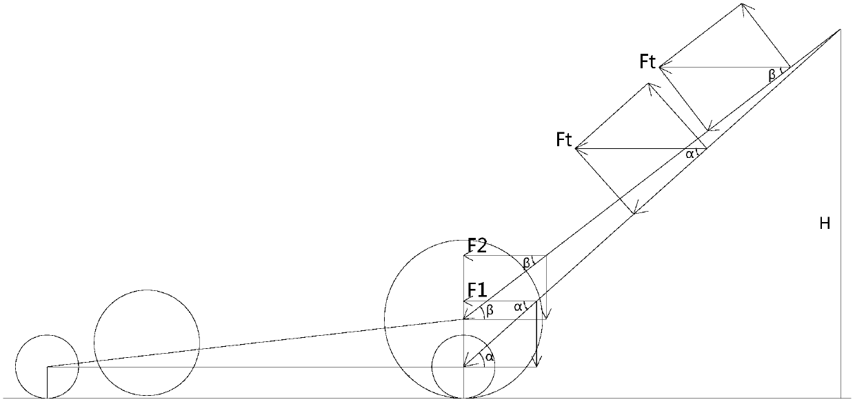
[0004] During the backward travel of the surface cleaning head, the user exerts a pulling force on the vacuum cleaner, typically the user will pull in an upward and rearward direction, which in some cases may move the support wheels on the rear of the surface cleaning head and the bottom of the housing Lifting away from the surface being cleaned, thereby reducing the sealing effect between the surface cleaning head and the surface being cleaned, resulting in a reduced partial vacuum created in the surface cleaning head, reducing suction performance

Method used


Image

  • Surface cleaning head
  • Surface cleaning head
  • Surface cleaning head

Examples


Embodiment Construction

[0026] In order to explain the overall concept of the present invention more clearly, the following will be described in detail by way of examples in conjunction with the accompanying drawings.

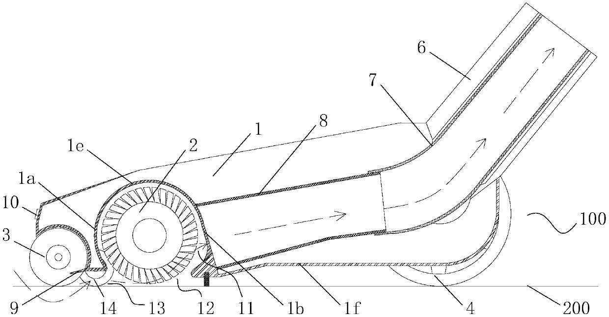
[0027] Surface cleaning heads are typically configured to contact a surface in order to clean the surface by using suction airflow, agitation, or a combination of suction airflow and agitation. The surface cleaning head is pivotally or steerably coupled by a swivel connection to a cleaning head joystick for controlling the surface cleaning head, the surface cleaning head may also be operated without a cleaning head joystick or handle. When the specified surface cleaning head is used, the side close to the surface to be cleaned is the lower side; when the specified surface cleaning head is used, the direction in which the user pushes the surface cleaning head forward is the front, and the user applies a pulling force to pull the surface cleaning head back in the direction of rear. As ...


PUM


Abstract

The invention discloses a surface cleaning head comprising a housing; the housing comprises a dust collection chamber, a brush roller, a front guide roller and one or more rear support wheels; the dust collection chamber is provided with an opening in the lower side of the housing; the brush roller is rotatably mounted in the dust collection chamber and at least a portion is close to the opening;the front roller is rotatably mounted on the housing, located in front of the brush roller and the opening and spaced apart from the brush roller, and the one or more rear support wheels are disposedbehind the housing and spaced apart from the brush roller; an inter-roller air passage is defined between the lower portion of the brush roller and the front guide roller, the outer diameter of the front guide roller is smaller than the outer diameter of the brush roller, the position of the lower bottom surface of the front guide roller is lower than the position of the lower bottom surface of the brush roller, and the outer diameter of the rear support wheel is larger than the outer diameter of the brush roller. The surface cleaning head in the invention integrally presents the form of low front and high rear, thereby facilitating ground operation of the surface cleaning head; the surface cleaning head has a good cleaning effect on corners with vertical surfaces as well as spaces such asfurniture and / or cabinets with low gaps, and no cleaning dead angles are left; and the surface cleaning head also has good ground operation performance.

Description

technical field [0001] The invention belongs to the technical field of cleaning equipment, in particular to a surface cleaning head for a vacuum cleaner. Background technique [0002] Vacuum cleaners using cyclonic separation devices are well known and are usually equipped with a surface cleaning head which is attached to the vacuum cleaner by means of a cleaning head lever. When the surface cleaning head is in use, the user applies force on the surface cleaning head whereby the surface cleaning head moves back and forth over the surface being cleaned and sucks in dirt and dust. [0003] Surface cleaning heads typically have a suction inlet facing the surface being cleaned and a suction chamber in communication with the suction inlet to draw air and dirt and dust to or through the surface cleaning head. Vertical surfaces such as walls and borders are often encountered in household cleaning, but the suction inlet at the bottom of the surface cleaning head cannot clean such c...

Claims


Application Information

Patent Timeline
Patent Type & Authority Applications(China)
IPC IPC(8): A47L9/06A47L9/00
CPCA47L9/009A47L9/0606
Inventor 王旭宁
Owner 尚科宁家(香港)股份有限公司
Learn More