Model construction and verification method for tooth wear difference analysis of high-feed milling cutter
A technology of analysis model and verification method, applied in the direction of geometric CAD, etc., can solve problems such as single maximum wear amount, inability to accurately describe the difference in the wear state of different cutter teeth, and inability to fully describe the wear state of the flank face
- Summary
- Abstract
- Description
- Claims
- Application Information
AI Technical Summary
Problems solved by technology
Method used
Image
Examples
Embodiment approach 1
[0048] Implementation Mode 1: The details are as follows:
[0049] 1. Identification method of influencing factors of tooth wear difference of high-feed milling cutter
[0050] In order to identify the factors affecting the difference in tooth wear of high-feed milling cutters, milling experiments with high-feed milling cutters were carried out. Before the start of each experiment, the tooth error of the milling cutter was measured. After the experiment, the collected milling vibration signals were filtered, and the maximum value, minimum value, effective value, main frequency and spectrum value of the milling vibration acceleration under different cutting strokes were extracted.
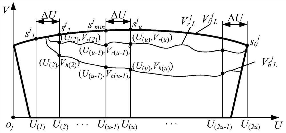
[0051] After the experiment, the flank wear morphology of each tooth of the high-feed milling cutter was detected, and the wear state diagram of the flank flank of the bottom edge of the tooth under different cutting stroke conditions was obtained. in point s j min with dot s j u The horizonta...
Embodiment 1
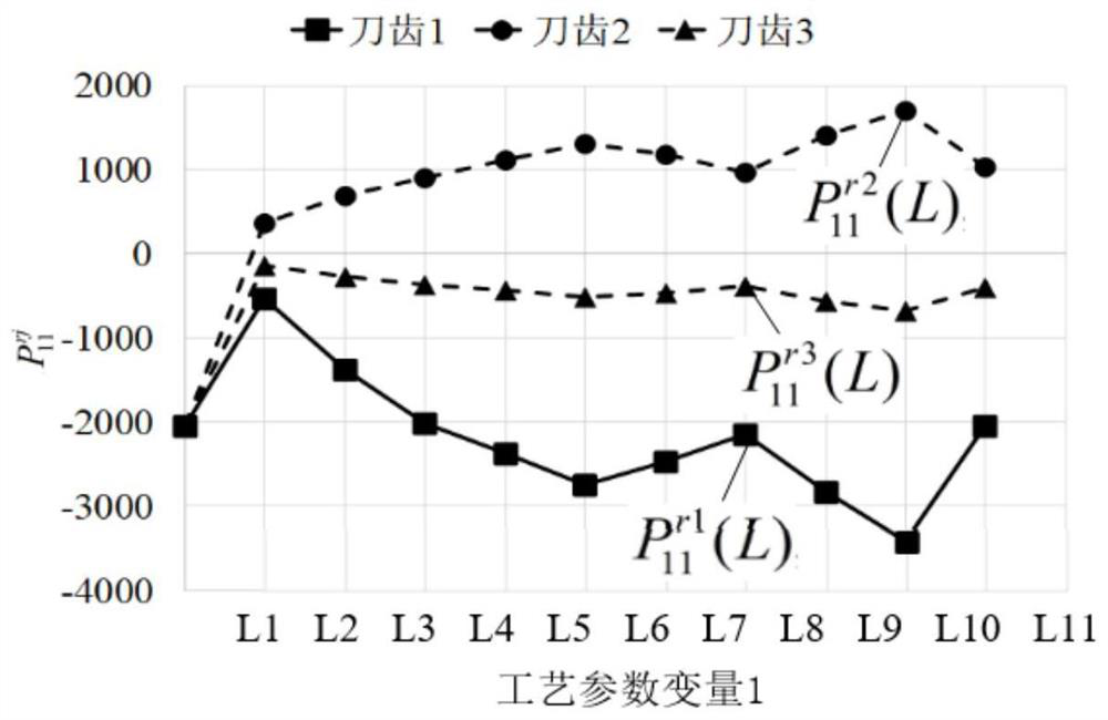
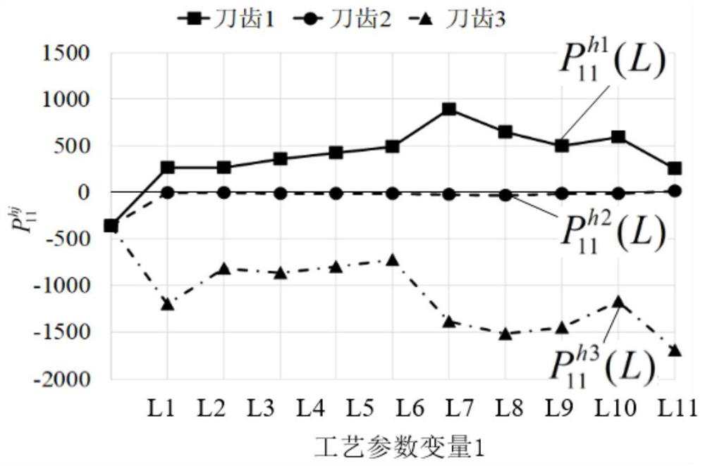
[0118] Implementation example 1: Identification method of influencing factors of tooth wear difference of high-feed milling cutter
[0119] In order to identify the factors affecting the difference in tooth wear of high-feed milling cutters, 10 sets of milling experiments were carried out using high-feed milling cutters (F2330) produced by Walter Company. The spindle speed n used in the experiments was 1143r / min, and the feed rate v f 500mm / min, milling depth a p 0.5mm, milling width a eis 16mm, and the milling stroke L is 0.5m, 1m,...,5m. Before the start of each group of experiments, the axial error of the milling cutter tooth (Δc j min ) and radial error (Δr 0 j ) for measurement and the measurement results are shown in Table 2.
[0120] The experiment of milling titanium alloy was carried out on the three-axis milling machining center (VDL-1000E) produced by Dalian Machine Tool Works. During the milling experiment of titanium alloy, the vibration signal generated b...
Embodiment 2
[0136] Implementation example 2: Construction method of high-feed milling cutter tooth wear difference analysis model
[0137] Describing the dynamic cutting behavior of milling cutters and cutter teeth during milling titanium alloys is the key to clarify the cause of differential wear of milling cutter cutter teeth. In order to obtain the change characteristics of the milling cutter’s cutting pose, quantitatively describe the dynamic cutting behavior of the milling cutter, and establish a cutting motion analysis model of the milling cutter, such as Figure 4 The meaning of each parameter in the figure is shown in Table 2.
[0138] Table 2 Explanation of variables in the analysis model of milling cutter tooth cutting motion
[0139]
[0140] Depend on Figure 4 It can be seen that the coordinate system o d v -a i v b i v c i v , o d -a i b i c i , o g -x g the y g z g The relationship between coordinate changes is shown in formula (6). Among them, the tra...
PUM
 Abstract
Description
Claims
Application Information
 - R&D
- Intellectual Property
- Life Sciences
- Materials
- Tech Scout
- Unparalleled Data Quality
- Higher Quality Content
- 60% Fewer Hallucinations
Browse by: Latest US Patents, China's latest patents, Technical Efficacy Thesaurus, Application Domain, Technology Topic, Popular Technical Reports.
© 2025 PatSnap. All rights reserved.Legal|Privacy policy|Modern Slavery Act Transparency Statement|Sitemap|About US| Contact US: help@patsnap.com


