Warp knitting machine with bilaterally-driven guide bar-bed assembly

A double-sided drive, warp knitting machine technology, applied in the field of warp knitting machines, can solve problems such as insufficient stability, and achieve the effects of easy high-speed operation, reduced vibration, and reduced noise pollution

Pending Publication Date: 2020-01-17
泉州鹏太机械有限公司
View PDF1 Cites 2 Cited by
  • Summary
  • Abstract
  • Description
  • Claims
  • Application Information

AI Technical Summary

Problems solved by technology

[0010] Therefore, the present invention provides a double-sided driven bar bed assembly swinging device, which solves the problem of insufficient stability of the bar part of the existing warp knitting machine during high-speed operation

Method used


Image

  • Warp knitting machine with bilaterally-driven guide bar-bed assembly
  • Warp knitting machine with bilaterally-driven guide bar-bed assembly
  • Warp knitting machine with bilaterally-driven guide bar-bed assembly

Examples


Embodiment 1

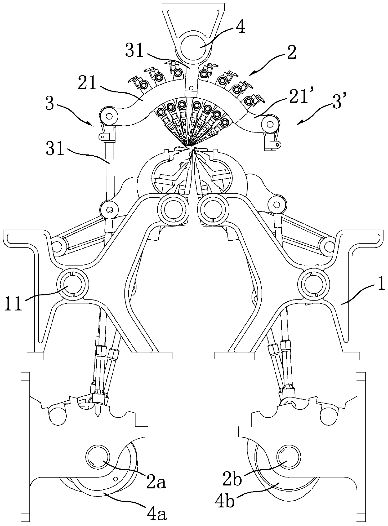
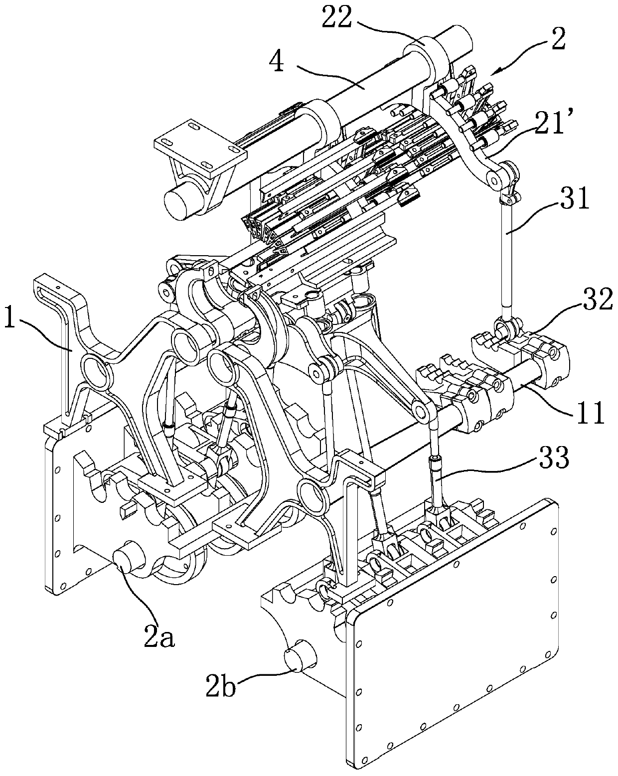
[0031] refer to Figure 2 to Figure 5 , a kind of warp knitting machine driven by both sides of the comb bed assembly, comprising a frame 1 and a comb bed assembly 2 installed on the frame 1, a main shaft one 2a, a main shaft two 2b and a motor one 3a as power, the main shaft One axial end of one 2a is connected to the output end of motor one 3a by transmission, and the main shaft one 2a is provided with three synchronously rotating cams one 4a. Establish connection; the main shaft 2b is provided with 3 cams 4b that rotate synchronously, each of the cams 4b is pivotally connected with the swing arm 21' on the other side of the comb bed assembly 2 through the transmission device 2 3', each of the The first cam 4a and the second cams 4b have the same circumferential profile along the circumferential direction, and the phase difference between the two is 180 degrees. The first main shaft 2a and the second main shaft 2b are synchronized by a synchronous mechanism. A pendulum shaf...

Embodiment 2

[0038] refer to Figure 8 , Compared with Embodiment 1, the end of the swing arm 21, 21' connected to the swing rod 31 in this embodiment is provided with five installation adjustment holes 211, and the swing rod is installed on one of the installation adjustment holes 211. This structure, when needed, can adjust the installation adjustment hole 211 where the swing rod 31 is located, and then realize the adjustment of the swing range structurally. The farther away from the installation adjustment hole of the balance shaft 4, the smaller the swing amplitude.

[0039] The present invention does not make specific statements on the loop forming device, etc. For details, refer to the applicant's prior application CN108642698A.


PUM


Abstract

The invention relates to the field of knitting machinery, in particular to a warp knitting machine with a bilaterally-driven guide bar-bed assembly, which comprises a frame, as well as a guide bar-bedassembly, a first spindle, a second spindle and a first motor serving as power, which are mounted on the frame; one axial end of the first spindle is in transmission connection with the output end ofthe first motor; the first spindle is provided with three to six first cams rotating in sync, each first cam is pivotally connected with a rocker of the guide bar-bed assembly through a first transmission device; the second spindle is provided with three to six cams rotating in sync; the second cams are pivotally connected with a rocker on the other side of the guide bar-bed assembly through a second transmission device, the first cams and the second cams have the same circumferential outline along the circumferential direction, the cams have a phase difference of 180 degrees, and the two spindles are synchronized through a synchronization mechanism. The warp knitting machine is applied to warp knitting equipment and provides a guide bar-bed assembly rocking device suitable for high-speedproduction.

Description

technical field [0001] The invention relates to the field of knitting machinery, in particular to a warp knitting machine driven by both sides of a bar bed assembly. Background technique [0002] The Jacquard warp knitting machine is a warp knitting machine with a Jacquard device, including a loop forming device, a bar device, and a transmission device. The Jacquard device is mainly used to drive the Jacquard needles to knit flowers. The pattern of knitting can be large. The shape is not limited. Among them, the knitting device includes symmetrical front and rear stripping parts, symmetrical front and rear needle bed parts and symmetrical front and rear sinking parts; The bar seat, the upper end of the bar bed assembly is hoisted on the upper swing shaft of the frame, the bar bar is installed on the bar bed assembly, and the guide needle is connected to the bar bar; the transmission device includes front and rear needle beds The front and rear needle bed transmission mecha...

Claims


Application Information

Patent Timeline
IPC IPC(8): D04B27/24
CPCD04B27/24
Inventor 王启超骆明彬陈浩
Owner 泉州鹏太机械有限公司
Why Eureka
Try Eureka