
Elevator cable system

A technology of elevators and communication cables, applied in the field of elevators, can solve the problems of slow data transmission speed of elevators, high cost of data transmission by control cables, and no accompanying cables, etc., to shorten the development cycle, save development time and costs, and reduce process flow Effect

Active Publication Date: 2021-03-23
ELECTRICITY FACILITIES GUANGRI GUANGZHOU CO LTD
View PDF3 Cites 0 Cited by
  • Summary
  • Abstract
  • Description
  • Claims
  • Application Information

AI Technical Summary

Problems solved by technology

[0006] The Chinese patent with the application number 201611103980.3 discloses a PLC technology-based elevator shaft data transmission device and transmission method, including A-end PLC access equipment and B-end PLC access equipment connected to the A-end PLC access equipment, Both the A-side PLC access device and the B-side PLC access device are equipped with a bus interface connected to the elevator control cabinet and car, a configuration management module, and a cable transmission carrier function module for transmitting analog signals or digital signals by means of carrier waves. The communication connection between the bus interface, the configuration management module and the cable transmission carrier function module also includes a power line for data transmission as a transmission carrier, and the data is transmitted between the A-side PLC access device and the B-end PLC access device through the power line, Adopting this invention can solve the technical problems of slow data transmission speed of elevators in the prior art and high cost of data transmission using control cables
[0007] These existing technologies do not provide a standard accompanying cable, which still requires millions of experiments for each accompanying cable before it can be used.

Method used


Image

  • Elevator cable system
  • Elevator cable system

Examples


Embodiment Construction

[0023] In order to make the above objects, features and advantages of the present invention more comprehensible, specific implementations of the present invention will be described in detail below in conjunction with the accompanying drawings. In the following description, numerous specific details are set forth in order to provide a thorough understanding of the present invention. However, the present invention can be implemented in many other ways different from those described here, and those skilled in the art can make similar improvements without departing from the connotation of the present invention, so the present invention is not limited by the specific embodiments disclosed below.

[0024] It should be noted that when an element is referred to as being “fixed on” or “disposed on” another element, it may be directly on the other element or there may be an intervening element. When an element is referred to as being "connected to" another element, it can be directly co...


PUM


Abstract

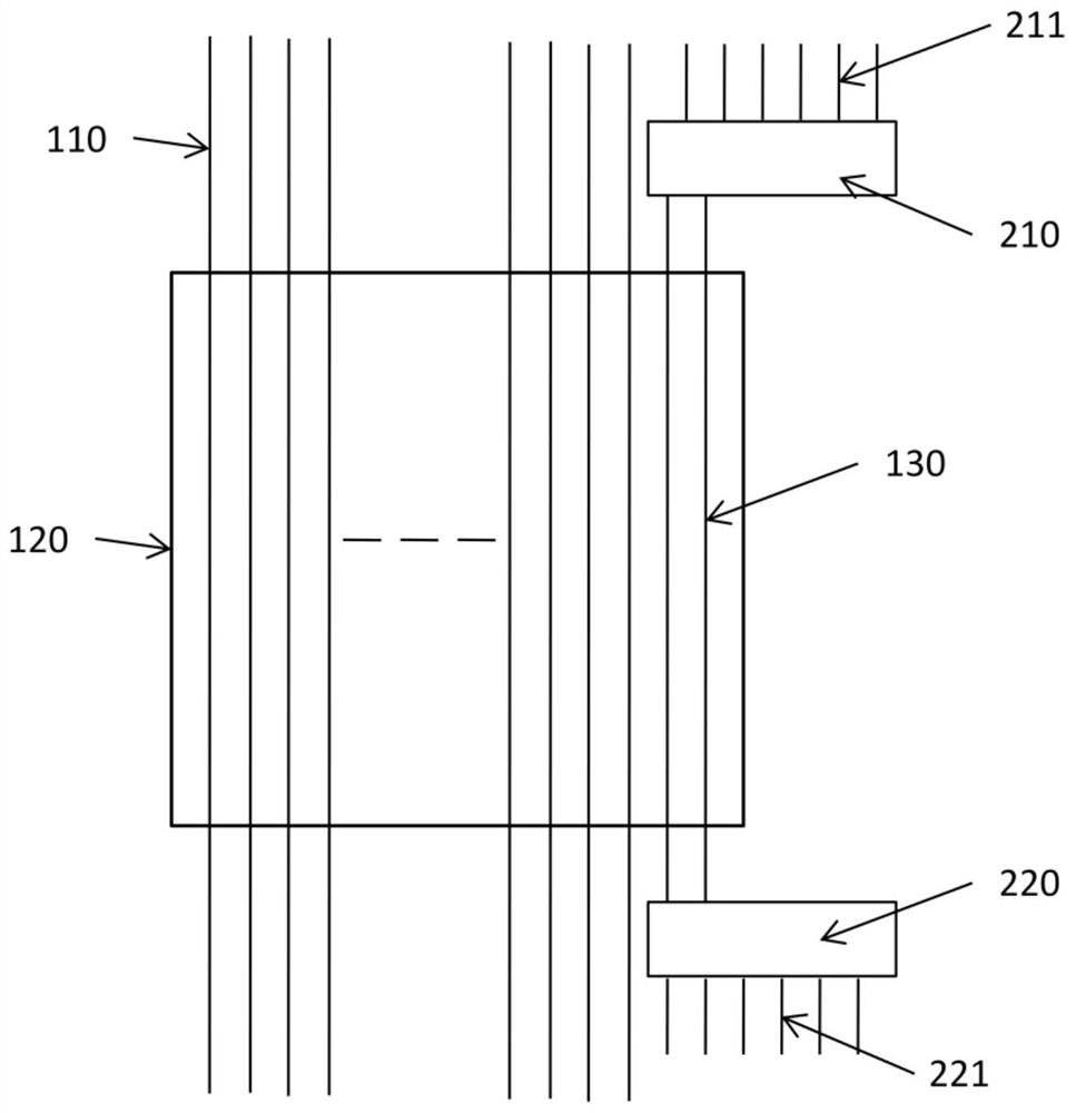
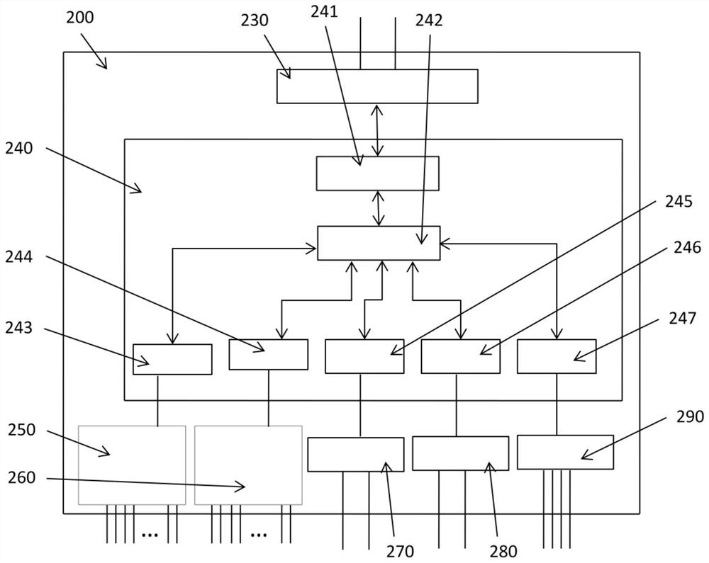
The invention relates to an elevator trailing cable system. The system involves a trailing cable and a pair of expansion boxes; the trailing cable is provided with core wires with fixed number, and the core wires comprise communication cables; and the pair of expansion boxes are arranged at the two ends of the trailing cable correspondingly, one of the expansion box is connected with the other expansion box through the communication cables, and the expansion boxes are further used for connecting expansion core wires. The invention provides a standard trailing cable product, the common problemscaused by non-standard products such as more than 3 million to 5 million bending experiments for each development of a trailing cable of an elevator shaft are avoided; the number of the wire cores inthe trailing cable is controlled, and excessive core wires do not need to be adopted, thereby reducing the weight of the trailing cable and reducing the cost of the trailing cable; the application ismore flexible, and the delay of signal transmission is controlled; the elevator trailing cable system can be used in cooperation with various different elevator types, the process flow is greatly reduced while diversified elevator function design is realized, the development time and cost are saved, batch production is facilitated, and the development cycle of the new elevator type is shortened.

Description

technical field [0001] The invention relates to the field of elevators, in particular to an elevator cable system. Background technique [0002] The elevator cable is a kind of cable for the elevator shaft, which is a very mature product. Elevator accompanying cable refers to the cable used to connect the elevator car and the elevator control room, including power supply circuit, control signal circuit, switch circuit and high-speed communication circuit, which is equivalent to a collection of a set of wires. Usually, according to different application requirements, the elevator accompanying cable is designed as a flat cable with 6 to 120 cores. [0003] The existing cable-mounted systems for elevator shafts are all based on the design requirements, and the number of cable core wires is determined according to the method of non-standard customization. As a result, the number of cores of the cables may be different for each type of elevator, and a new model is developed. Fo...

Claims


Application Information

Patent Timeline
Patent Type & Authority Patents(China)
IPC IPC(8): B66B7/00B66B1/06
CPCB66B1/06B66B7/00B66B2201/30
Inventor 邓志辉樊京路李钟东朱子裕罗晓兰
Owner ELECTRICITY FACILITIES GUANGRI GUANGZHOU CO LTD
Learn More