
Leak detection method and device for brake system

A brake system and leak detection technology, which can be used in brake safety systems, railway vehicle testing, and by measuring the rate of increase and deceleration of fluids, can solve time-consuming and labor-intensive problems

Active Publication Date: 2020-11-27
QINGDAO SRI TECH CO LTD
View PDF8 Cites 0 Cited by
  • Summary
  • Abstract
  • Description
  • Claims
  • Application Information

AI Technical Summary

Problems solved by technology

Method used


Image

  • Leak detection method and device for brake system
  • Leak detection method and device for brake system
  • Leak detection method and device for brake system

Examples


Embodiment Construction

[0072] The following will clearly and completely describe the technical solutions in the embodiments of the present invention with reference to the accompanying drawings in the embodiments of the present invention. Obviously, the described embodiments are only some, not all, embodiments of the present invention. Based on the embodiments of the present invention, all other embodiments obtained by persons of ordinary skill in the art without making creative efforts belong to the protection scope of the present invention.

[0073] The braking system involved in the present invention can be a hydraulic braking system in the prior art, wherein the schematic diagram of the hydraulic braking system can be as follows figure 1 as shown, figure 1 01 stands for motor; 02 stands for oil pump; 03 stands for relief valve; 04 and 17 stands for filter; 05 stands for one-way valve; 06 and 15 stands for pressure switch; 07 and 18 stands for pressure detection port; 09 stands for two-position tw...


PUM


Abstract

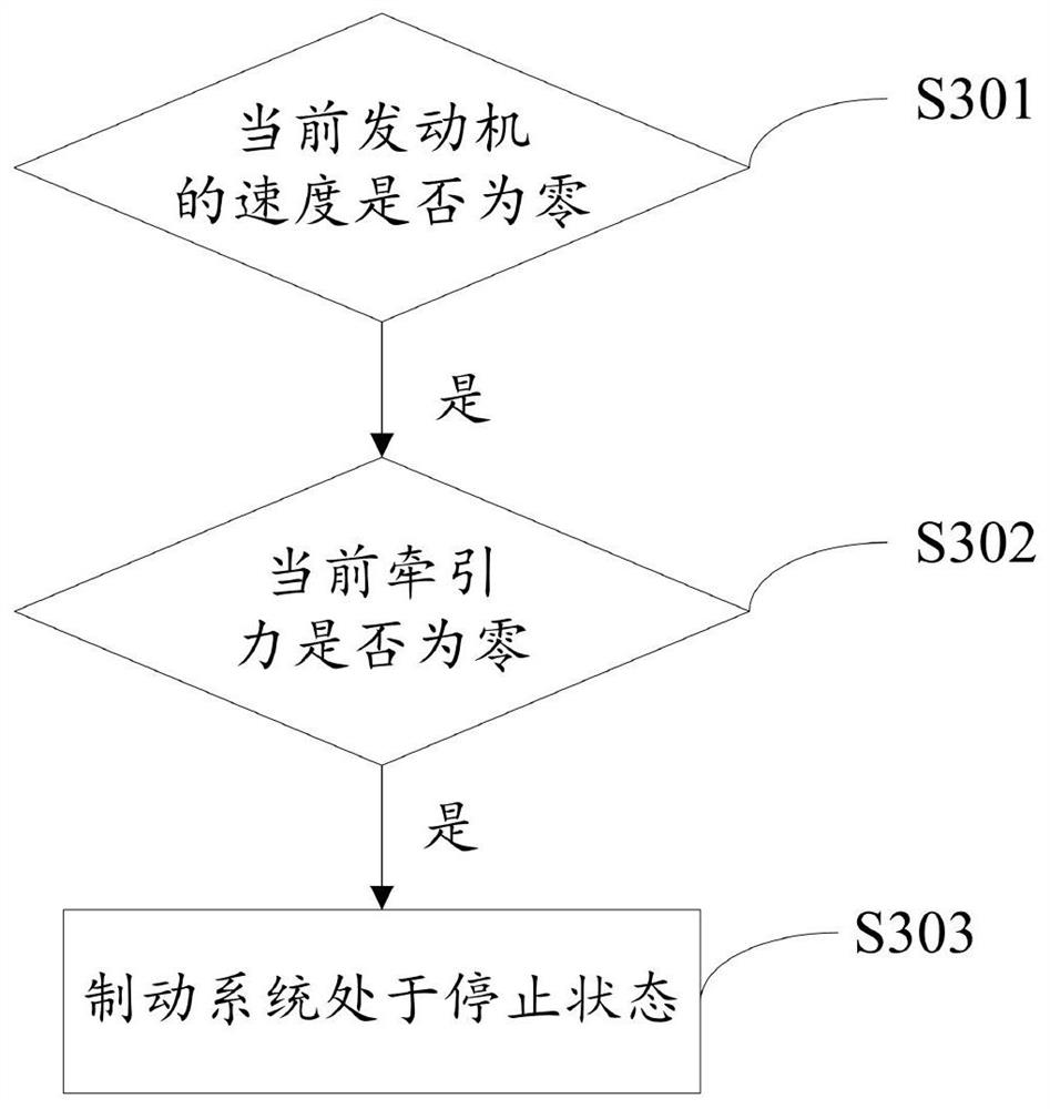
The invention provides a leakage detection method and device for a brake system, and the method comprises the steps of firstly, receiving a leakage testing instruction; then judging whether the brakesystem is in a stop state or not; when it is judged that the brake system is in the stop state, carrying out pressure adjustment on a brake cylinder; if the pressure value of the brake cylinder meetsthe leakage test requirement, judging whether the energy accumulator and the brake cylinder have leakage faults or not; and if it is judged that any one of the energy accumulator and the brake cylinder has the leakage fault, indicating that the brake system has the leakage fault. Therefore, the method for automatically and intelligently detecting the leakage of the brake system is realized.

Description

technical field [0001] The invention relates to the technical field of urban rail train control, in particular to a leakage detection method and device for a braking system. Background technique [0002] The braking system is a key subsystem in the train system. Whether the performance of the braking system is stable or not directly determines the overall safety performance of the train. [0003] At present, when checking the leakage of the brake system, it is necessary to separately detect the leakage of the accumulator pipeline and the brake pipeline in two steps, and the manual pump needs to be shaken hundreds of times to reach the specified test pressure. Very time-consuming and laborious. After the pressure stabilizes, record the pressure of the brake pipeline, and then record the brake management pressure after standing for a period of time, and calculate whether the pressure drop of the brake pipeline is within the range required by the standard. If it is not within ...

Claims


Application Information

Patent Timeline
Patent Type & Authority Patents(China)
IPC IPC(8): B60T17/22G01M3/26G01M17/08
CPCB60T17/22G01M3/26G01M17/08
Inventor 唐亮刘泉毛莉胡斌李杰
Owner QINGDAO SRI TECH CO LTD
Learn More