An automatic cutting equipment for hardware pipe fittings

A technology for cutting equipment and pipe fittings, which is applied in the field of automatic cutting equipment for hardware pipe fittings, can solve the problems of large manual labor, unfavorable production efficiency, and low work efficiency, and achieve a high degree of automation, convenient feeding and cutting, and improve work efficiency. Effect

Active Publication Date: 2020-08-14
苏州杰安培机电有限公司
View PDF8 Cites 0 Cited by
  • Summary
  • Abstract
  • Description
  • Claims
  • Application Information

AI Technical Summary

Problems solved by technology

[0003] Existing hardware pipe fittings need to be cut during processing or use. The existing cutting device is a process of manually placing, cutting, taking and re-releasing the pipes one by one. The processing is complicated and the manual labor is large. Moreover, the work efficiency is low, which is not conducive to improving production efficiency

Method used


Image

  • An automatic cutting equipment for hardware pipe fittings
  • An automatic cutting equipment for hardware pipe fittings
  • An automatic cutting equipment for hardware pipe fittings

Examples


Embodiment 1

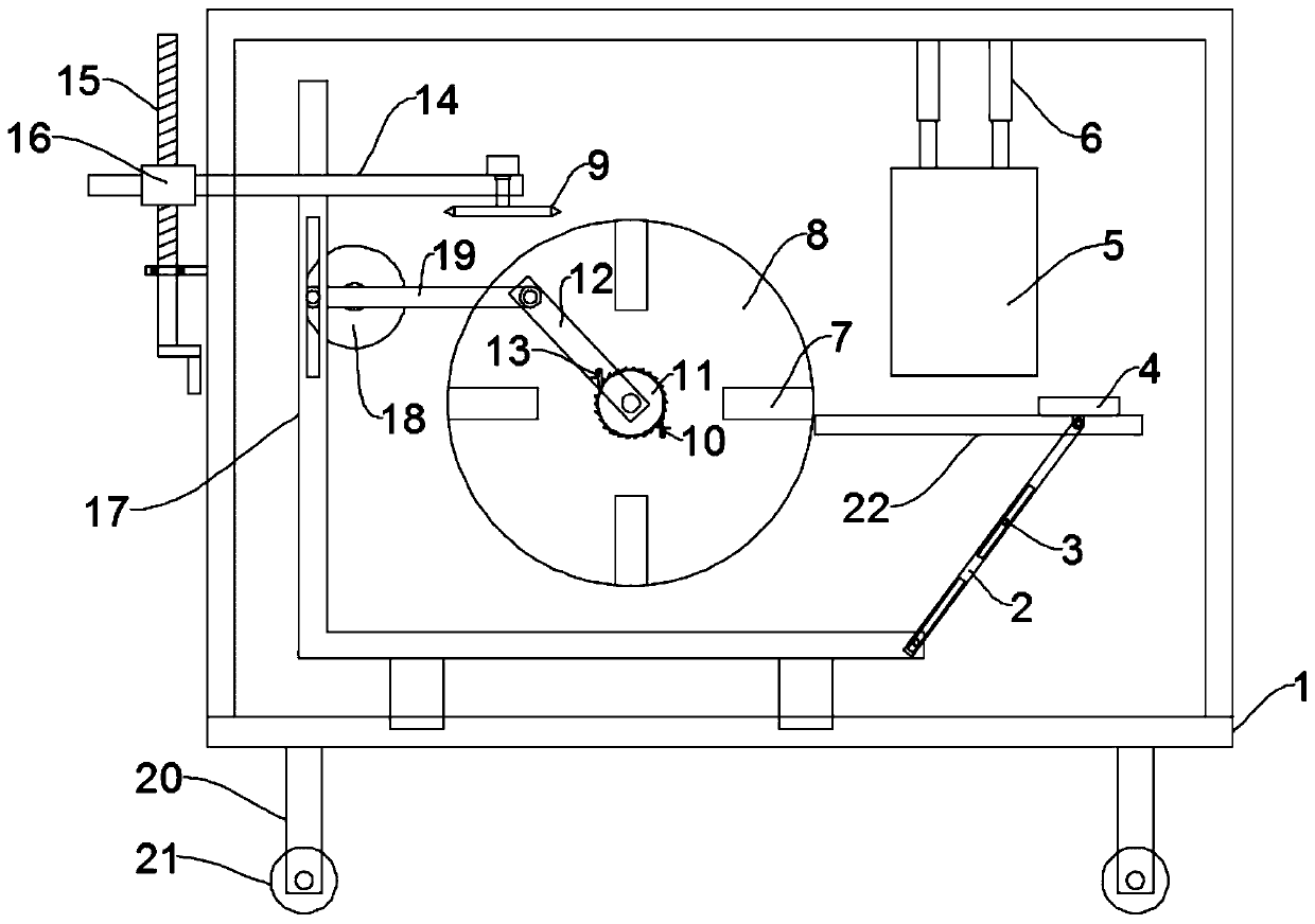
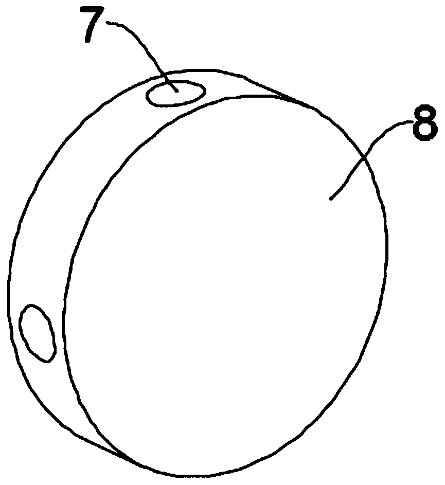
[0025] see Figure 1~2 , in the embodiment of the present invention, an automatic cutting equipment for metal pipe fittings, including a frame 1 and a cutting assembly 9, support legs 20 are evenly and symmetrically installed on the bottom of the frame 1, and rollers 21 are installed at the bottom of the support legs 20, the The roller 21 is a self-locking roller, and the cutting assembly 9 includes a cutting disc 18 and a drive motor for driving the disc 18 to rotate, and also includes a conveying mechanism that automatically transports the pipe to the cutting station for the cutting assembly 9 to cut, The conveying mechanism includes a drum 8, a pipe groove 7 provided on the drum 8 for accommodating pipe fittings, a feeding assembly for feeding pipe fittings into the pipe groove 7, and a driving mechanism for driving the drum 8 to rotate intermittently, The drum 8 is rotatably mounted on the frame 1, the feeding assembly includes a support plate 22, a hopper 5, a push block ...

Embodiment 2

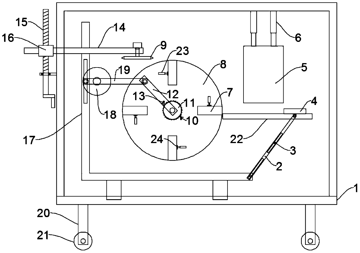
[0028] see image 3The difference between this embodiment of the present invention and Embodiment 1 is that further, in order to be able to adapt to pipes of different diameters, a second electric push rod 23 is installed on one side of the pipe groove 7 in the drum 8, and the second electric push rod 23 is installed on the side of the pipe groove 7. The end of the telescopic rod of the push rod 23 extends to the pipe groove 7 and is equipped with a positioning plate 24, which is stretched or shortened by the second electric push rod 23, so that the positioning plate 24 is pressed against pipe fittings of different diameters to facilitate cutting.

[0029] The working principle of the present invention is: when the present invention is in use, start the motor, the motor drives the disc 18 to rotate, the disc 18 drives the cylindrical pin to revolve, and the cylindrical pin drives the L-shaped rod 17 to reciprocate left and right, and the L-shaped rod 17 passes through the conne...


PUM


Abstract

The invention discloses automatic cutting equipment for hardware pipe fittings. The equipment comprises a rack, a cutting assembly and a conveying mechanism for automatically conveying the pipe fittings to a cutting station for cutting by the cutting assembly. The conveying mechanism comprises a rotary drum, a pipe groove formed in the rotary drum and used for containing the pipe fittings, a feeding assembly used for feeding the pipe fittings into the pipe groove and a driving mechanism used for driving the rotary drum to intermittently rotate, wherein the rotary drum is rotationally installedon the rack; the driving mechanism comprises a ratchet wheel, a power rod, a power pawl, a check pawl and a power mechanism used for driving the power rod to swing in a reciprocating mode, and the power mechanism comprises a motor, a disc, an L-shaped rod and a connecting rod; and the feeding assembly comprises a supporting plate, a hopper, a pushing block and a pushing mechanism for pushing thepushing block to reciprocate. The conveying mechanism for automatically conveying the pipe fittings to the cutting station for cutting by the cutting assembly is included, the pipe fittings can be continuously cut, the automation degree is high, the labor intensity of workers is reduced, and the working efficiency is improved.

Description

technical field [0001] The invention relates to the technical field of hardware processing, in particular to an automatic cutting equipment for hardware pipes. Background technique [0002] Traditional hardware products, also known as "hardware". Refers to the five metals of gold, silver, copper, iron, and tin. After manual processing, it can be made into works of art or metal devices such as knives and swords. Hardware in modern society is more extensive, such as hardware tools, hardware parts, daily hardware, construction hardware and security supplies. [0003] Existing hardware pipe fittings need to be cut during processing or use. The existing cutting device is a process of manually placing, cutting, taking and re-releasing the pipes one by one. The processing is complicated and the manual labor is large. And work efficiency is low, is unfavorable for improving production efficiency. Contents of the invention [0004] The purpose of the embodiment of the present i...

Claims


Application Information

Patent Timeline
Patent Type & Authority Patents(China)
IPC IPC(8): B23D21/00B23D33/02B23D33/00
CPCB23D21/00B23D33/00B23D33/02
Inventor 沈海红钱巧观
Owner 苏州杰安培机电有限公司
Why Eureka
Try Eureka