
Methods and apparatus for locating RFID tags

A technology of RFID tags and tags, applied in the directions of positioning, utilizing re-radiation, substation devices, etc.

Pending Publication Date: 2020-01-14
AUTOMATION INC
View PDF0 Cites 5 Cited by
  • Summary
  • Abstract
  • Description
  • Claims
  • Application Information

AI Technical Summary

Problems solved by technology

These ghost images could fool the receiver into determining the presence of additional RFID tags

Method used


Image

  • Methods and apparatus for locating RFID tags
  • Methods and apparatus for locating RFID tags
  • Methods and apparatus for locating RFID tags

Examples


Embodiment Construction

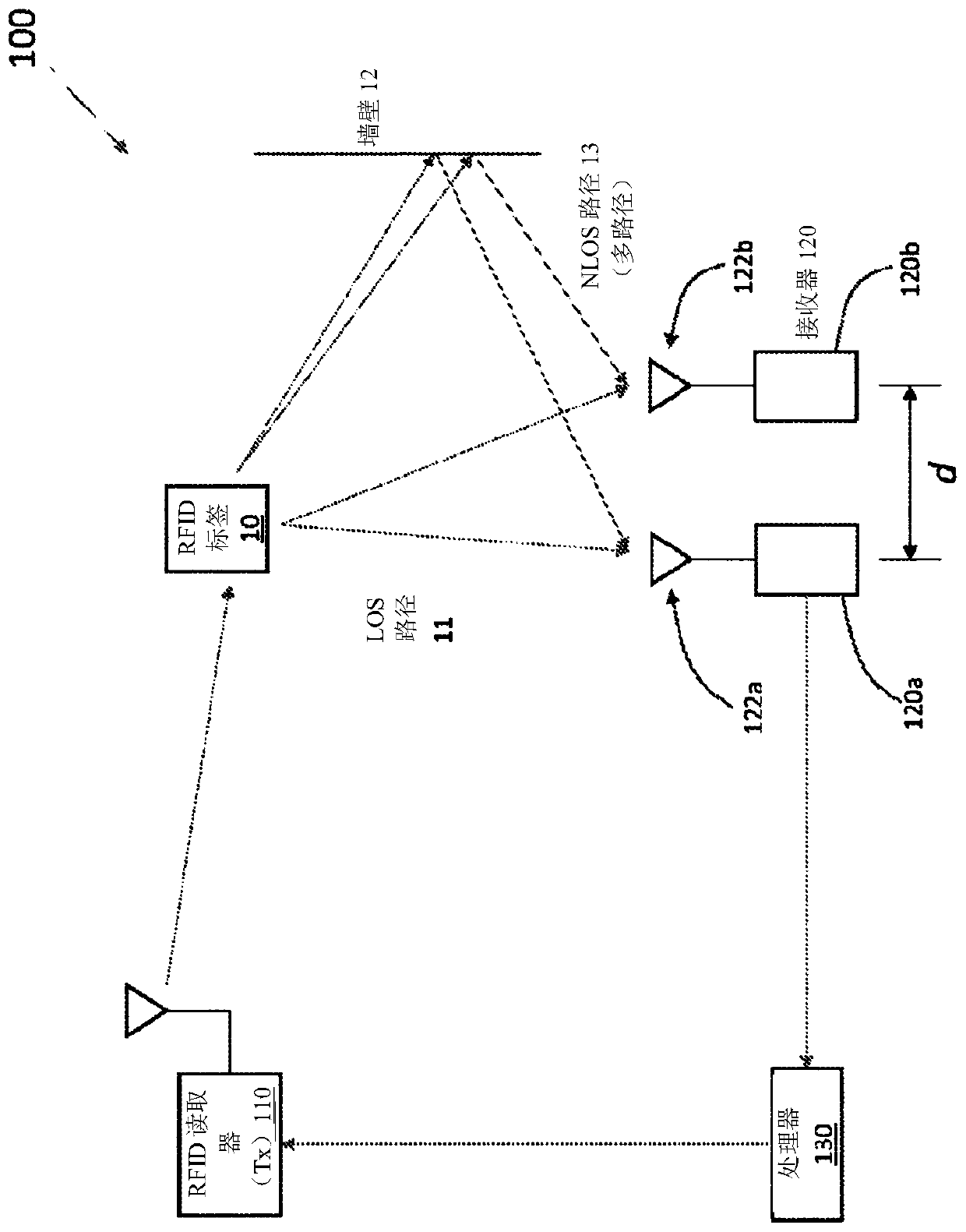
[0036] So far, RFID positioning technology has not lived up to expectations. Combined with computer vision technology, the RFID location technology of the present invention provides unprecedented speed and accuracy. In fact, it can be as much as 300 times more accurate than traditional RFID positioning technology. For example, the systems and methods disclosed below may be used to position an RFID tag within 50 cm, 40 cm, 30 cm, 25 cm, 20 cm, 15 cm, 10 cm, 5 cm, or 2.5 cm of its actual location. With this speed and accuracy, it can be used to track even the slightest movement of RFID-tagged items in real time. This level of speed and precision enables items to be found and restocked almost instantly, and to track interactions between RFID tags. For RFID tags on products in stores, this generates item-by-item data about customer interactions with products and enables autonomous checkout.

[0037] Unless physically incompatible, all techniques disclosed herein can be used wit...


PUM


Abstract

A radio frequency identification (RFID) system includes an array of antennas to distinguish line-of-sight (LOS) paths from non-line-of-sight (NLOS) paths. The distance between adjacent antennas in thearray of antennas is less than half the wavelength of the radio frequency (RF) signal of the system. Each antenna in the antenna array is also digitally controlled to change relative phase differenceamong the antennas, thereby allowing digital steering of the array of antennas across angles of arrival (AOAs) between 0 and pai. The digital steering generates a plot of signal amplitudes as a function of AOAs. LOS paths are distinguished from NLOS paths based on the shapes (e.g., depth, gradient, etc.) of local extremes (e.g., maxima or minima) in the plot.

Description

[0001] Cross References to Related Applications [0002] This application claims priority under U.S. 35 U.S.C. § 119(e) to U.S. Application No. 62 / 577,530, filed October 26, 2017, and U.S. Application No. 62 / 477,796, filed March 28, 2017. These applications are hereby incorporated by reference in their entirety. Background technique [0003] Radio Frequency Identification (RFID) technology has applications in many business areas, such as access control, animal tracking, security and toll systems. A typical RFID system includes tags (also called transponders) and readers (also called interrogators). The reader includes an antenna to transmit radio frequency (RF) signals and to receive RF signals reflected or transmitted by the tag. Tags may also include an antenna and an Application Specific Integrated Circuit (ASIC) or microchip. A unique electronic product code can be assigned to a label to distinguish it from other labels. [0004] RFID systems can use active tags or pa...

Claims


Application Information

Patent Timeline
Patent Type & Authority Applications(China)
IPC IPC(8): G01S5/02G06Q10/08
CPCG01S5/0273G01S5/04G01S13/878G01S13/82G01S5/0284G01S5/0221G01S5/0294G06Q10/087G06Q20/203H04Q2209/47H04Q2209/84G06Q30/06H04B1/0007G07G1/009G01S5/02G06Q10/08G01S5/0218G06K7/10297G06K7/10465
Inventor S·休伊特A·布莱尔K·塞夫M·墨菲M·威依迈T·艾德林
Owner AUTOMATION INC
Learn More