
Camshaft bearing pedestal

A bearing seat and camshaft technology, applied in the lubrication of valve accessories, engine components, machines/engines, etc., can solve the problems of the overall weight and length of the engine, the difficulty in the design of the lubricating oil channel of the camshaft, and the limitation of the application range of the engine. Achieve the effect of avoiding manufacturing difficulty, simple processing and low processing and manufacturing cost

Pending Publication Date: 2020-01-14
KUNMING YUNNEI POWER +1
View PDF0 Cites 3 Cited by
  • Summary
  • Abstract
  • Description
  • Claims
  • Application Information

AI Technical Summary

Problems solved by technology

For this kind of camshaft bearing housing structure integrated with the cylinder head, the design of the lubricating oil channel of the camshaft is relatively difficult due to the large volume of the integrated bearing housing and the cylinder head, and the cost of processing the lubricating oil channel is very high, and It also makes it difficult to cast the cylinder head
At the same time, this structure of the camshaft bearing seat will also affect the arrangement of the cylinder head bolts, sometimes causing the bolt holes on the bearing seat (such as the bolt holes connecting the bearing cap) to overlap with the positions of the cylinder head bolts, and in order to prevent The overlap between the bolt holes on the bearing seat and the cylinder head bolts often requires increasing the length of the cylinder head, which will increase the overall weight and length of the engine, thereby limiting the application range of the engine

Method used


Image

  • Camshaft bearing pedestal
  • Camshaft bearing pedestal

Examples


Embodiment Construction

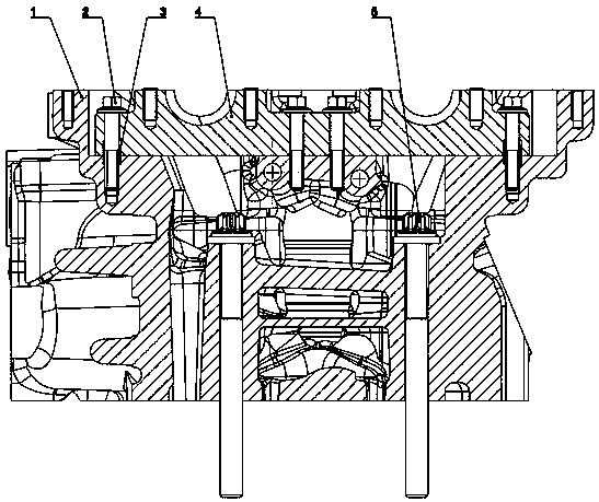
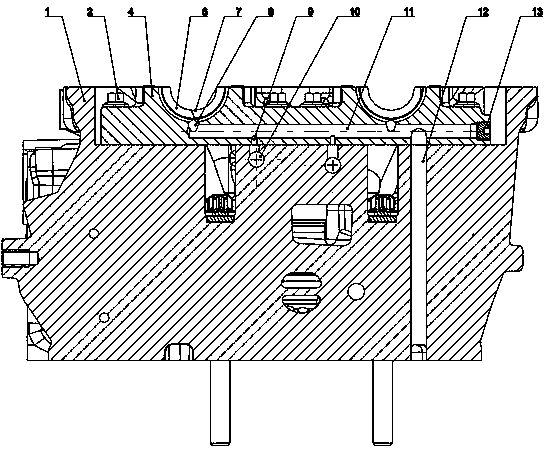
[0015] The following will clearly and completely describe the technical solutions in the embodiments of the present invention with reference to the accompanying drawings in the embodiments of the present invention. Obviously, the described embodiments are only some, not all, embodiments of the present invention. Based on the embodiments of the present invention, all other embodiments obtained by persons of ordinary skill in the art without making creative efforts belong to the protection scope of the present invention. In the following description, in order to clearly show the structure and working method of the present invention, the accompanying drawings will be used as the basis to describe with the help of many directional words, but "front", "rear", "left", "right", Words such as "up" and "down" are to be understood as convenient terms, and should not be understood as restrictive terms.

[0016] Figure 1-2 The camshaft bearing block shown is connected to the cylinder he...


PUM


Abstract

The invention discloses a camshaft bearing pedestal. The camshaft bearing pedestal is convenient to manufacture. The camshaft bearing pedestal comprises a bearing pedestal body located on the upper portion of a cylinder cover during assembling, two camshaft bearing holes are formed in the upper end of the bearing pedestal body, a positioning hole and a bolt hole used for connecting with a cylindercover are formed in the bearing pedestal body, lubricating oil grooves are formed in the walls of the camshaft bearing holes, a transverse bearing pedestal oil way is arranged at the position, located below the lubricating oil grooves, in the bearing pedestal body, two throttling holes which are downwards through are formed in the bearing pedestal oil way, lower port portions of the throttling holes correspond to a cylinder cover oil way on the cylinder cover, two oiling holes communicating with the two lubricating oil grooves are formed in the bearing pedestal oil way, and one end of the bearing pedestal oil way is through, and is provided with a plug; and after the bearing pedestal body is assembled with the cylinder cover, the top face of the bearing pedestal body and the top face of the cylinder cover are located on the same plane. Machining is easy, and manufacturing cost is low.

Description

technical field [0001] The invention relates to the technical field of engines, in particular to a camshaft bearing seat. Background technique [0002] Most of the existing overhead camshaft engine camshaft bearing housings are separated up and down, and are composed of an upper bearing cover and a lower bearing housing. That is to say, the lower bearing seat is generally integrated on the cylinder head, and the upper bearing cover is fastened to the lower bearing seat by bolts. For this kind of camshaft bearing housing structure integrated with the cylinder head, the design of the lubricating oil channel of the camshaft is relatively difficult due to the large volume of the integrated bearing housing and the cylinder head, and the cost of processing the lubricating oil channel is very high, and It also makes it difficult to cast the cylinder head. At the same time, this structure of the camshaft bearing seat will also affect the arrangement of the cylinder head bolts, som...

Claims


Application Information

Patent Timeline
Patent Type & Authority Applications(China)
IPC IPC(8): F01L1/047F01M9/10F02F1/24
CPCF01L1/047F01M9/10F01M9/102F02F1/24
Inventor 崔丛敏杨波赵霄鹏孔凡良
Owner KUNMING YUNNEI POWER
Learn More